Problem:
Possible Causes & Resolutions:
Problem:
Possible Causes & Resolutions:
Please follow the below instructions carefully:
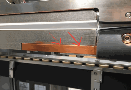
Take off the lower weld roll, unplug the grey water tube ø 10 mm labeled with “àWR” directly at the flow switch S26, and blow into the tube with air pressure. Check the out-going air-pressure at the free hole in the lower weld arm (supply for lower weld roll). If the circuit is free, you feel an equal air pressure (like on the output of the air gun) on your finger tip. If you recently took off the lower weld arm, there might be a problem with one or both o-ring seals between arm and upper bus bar:
Please check them if needed !
Before re-connecting both grey tubes ø 10 mm, blow into one tube again by air-pressure, and feel the equal air-pressure on the other tube by your finger tip. If it’s ok, correctly connect both tubes again.
Problem:
Possible Cause:
Check:

NOTE:
A minimum of marks will always be left on the canbody, because the CM21 is a semiautomatic welding machine with a clamping system.
But you can minimize the marks on the canbody, we can show you how.
Loose all four allan screws.
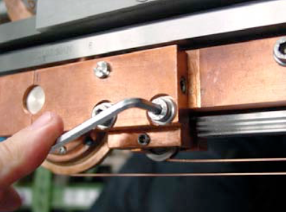
Adjust the nose/headpiece through the excenter with a screwdriver and then tighten all screws again.

Possible causes:
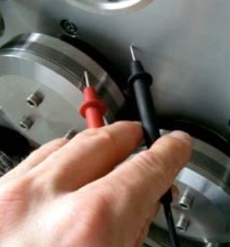
Use a common Ohmmeter, as you can see on the picture.
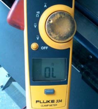
Measure the resistance between left carbide ring and main aluminum plate.
The measuring result on the Ohmmeter must be endless!
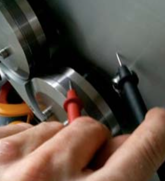
Measure the resistance between left carbide ring and main aluminum plate.
The measuring result on the Ohmmeter must be endless!
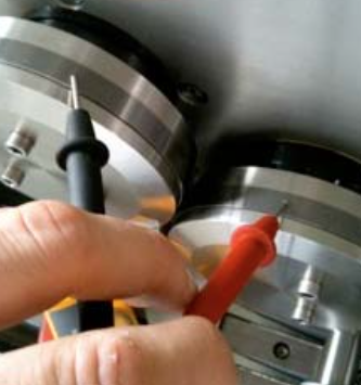
Measure between left and right carbide ring. The result on the Ohmmeter must be endless! This step is to ensure the proper insulation of both rear insulation rings around the taper roller bearings!
The picture shows the correct measuring result on the screen of the Ohmmeter for all three test points!
Download PDF here
=> How to adjust below, have a look at the manual!
Transformer step: 1 (if other is chosen, mention it)
Air supply: min. 4 bar and dry/clean! Check if water is in the tank, if yes, please mention
it, and if the filter is still in.
It may happen that an air regulator is damaged/not working properly, due to
water or dirt.
Copper wire profile: 2.05 +/- 0.03 mm
Welding roller grooves: width 2.10 mm, depth 0.40 mm
Edges should not be sharp, grind them manually!
Welding speed: See display frequency inverter, 50 – 55Hz (10 – 12m/min)
Above 12m/min micro leakages can appear!
Welding pressure: 1.7 – 2.0 bar (35-40 daN/kg)
– Set the ball joints on both central pressure cylinder (piston in top position):
Measure from end of ball joint to the begin of piston, it must be 22 mm or until the steel bar (of pressure link) is laying parallel to the base alu-plate
=> Target: Distance between pressure link rollers and groove of clamp bar around 0.5 mm
– Z-bar must be mounted parallel to top alu-plate
=> Measure with depth gauge left and right!
=> Measure the isolation between Z-bar and top alu-plate!
– Precise guide-bar (underneath Z-bar) must be positioned and mounted parallel to Z-bar => Measure with depth gauge left and right!
– Mount lower weld arm to Z-bar
=> Measure the isolation between Z-bar and lower weld arm
– Mount the lower weld roll, and set the height: Top point of weld roll (incl. copper wire) must be on the same height with center of Z-bar, or bottom side of upper Z-bar groove!
=> Depending on form of can body after welding!
– Move the upper excenter-shaft (rear axle of big alu-block which holds the upper weld roll), until the center of the upper weld roll stays around 1 – 2 mm behind the center of the lower weld roll
=> Helps to keep the overlap!
– Mount the small bearings on to inner and outer little shafts on the Z-bar
=> Lateral play of bearing shall be around 0.1 mm
– Mount the (brown) bottom base-plate onto both precise-carriages
=> Make sure that all 4 pins in the base-plate touch the precise-carriages inside!
– Start to mount the watercooled clamp-bars:
Place the outer / bottom clamp-bar ontop of bearings, move the bar forward and backward, and check whether the bearings are running freely in the groove
– Mount the alu-support between clamp-bar and bottom base-plate, and tight all four M6 screws slightly. Move the carriage forward and backward, and tight the screws step by step.
=> Whenever the clamp-bar is tightened, and the carriage is moving forward and backward, there should no resistance be felt during movement!
– Same procedure with inner bottom clamp-bar. Before lock the rear screws, mount the stainless steel plate on the front end of both bars and make sure that both bars are in line! Do not fully tight the M5 lock-nuts!
– Set the upper front pressure link:
Rear turning point must be free of play, see the assembling drawing for further information
– Tight the center grub screw M8, until they touch the Z-bar slightly
– Measure with depth gauge between front end of pressure link to Z-bar: Result should be 18.2 +/- 0.1 mm. If you have a different measure, change them by moving the grub screws.
– Place the outer upper clamp bar, move both sliding rollers from both pressure links into the groove, and tight both M6 screws on the rear vertical support rail. Measure between clamp bar and Z-bar should be 30.3 mm, see also in the assembling drawing. If not yet, loose the M6 screws and move the support again.
– Same procedure with inner upper clamp-bar.
– Connect the cylinder (piston in top position) wit the upper clamping bar, and adjust the ball joint until the distance between the upper and lower clamping-bar measures 1.0 +0.2/-0.0 mm
– Same setting to be done with the cylinder inside.
– If everything is fine the gap between the clamp bars in the front in and outside is also 1.0 +0.2/0.0 mm
– Finally check the clamping-force efficiency of the inner and outer clamping pairs: Air-pressure between 3 to 4 bars.
– Place a tin plate in the outer inner Z-bar groove, close the bars, and try to pull the tin plate out of groove by hand
=> The force on both sides should be as equal as possible.
We recommend following maintenance procedures:
Order numbers:
Safety data sheets see below:
