Problem:
Circuit breaker Q5 trips when the machine is switched on or during production.
Possible Causes or Resolutions:
Problem:
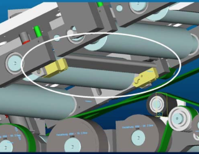
All drives are starting correctly, but the vacuum and welding current are not active.
Possible Causes & Resolutions:
Problem:
After main switch off and on again, HMI piece counter values and settings are lost or old recipes are loaded.
Possible Causes & Resolutions:
Problem:
Downstacker motor doesn’t move correctly to the reference position, stops or suddenly changes the direction of rotation. Display of servo controller U16 shows „IMax“ or „P03 trip“.
Possible Causes & Resolutions:
To check:
Problem:
Machine stops and message „Pacemaker: Profibus communication error“ is displayed.
Possible Causes & Resolutions:
Problem:
Possible causes & resolutions:
Please follow the below instructions carefully:
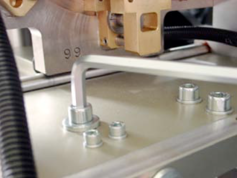
Take off the lower weld roll, unplug the grey water tube ø 10 mm labeled with “àWR” directly at the flow switch S26, and blow into the tube with air pressure. Check the out-going air-pressure at the free hole in the lower weld arm (supply for lower weld roll). If the circuit is free, you feel an equal air pressure (like on the output of the air gun) on your finger tip. If you recently took off the lower weld arm, there might be a problem with one or both o-ring seals between arm and upper bus bar:
Please check them if needed !
Before re-connecting both grey tubes ø 10 mm, blow into one tube again by air-pressure, and feel the equal air-pressure on the other tube by your finger tip. If it’s ok, correctly connect both tubes again.
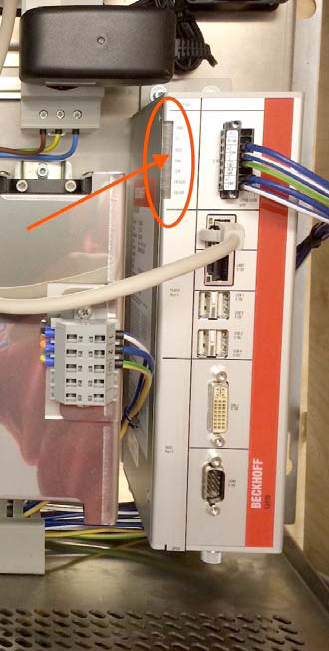
Click here for the status LED’s of the Beckhoff PC and how to access the PC in case of a trouble shooting.
Possible causes:
Possible cause:
The upper pendulum roller might be not leveled properly. When regrooving the upper disc for example 0.50 mm in diameter, the height of the pendulum rollerhead must be reduced 0.25 mm. This can be done by the M10 screw on the back side.
See also in the manual X1 how to reset the upper pendulum rollerhead.
NOTE: The description manual is based on a CM X1 welder, but it works very similar for our other welders.
ATTENTION: Do not touch the red marked screws!
Possible causes:
Before you change the transformer step switch off first the external supply!!!
Download PDF english
Download PDF chinese
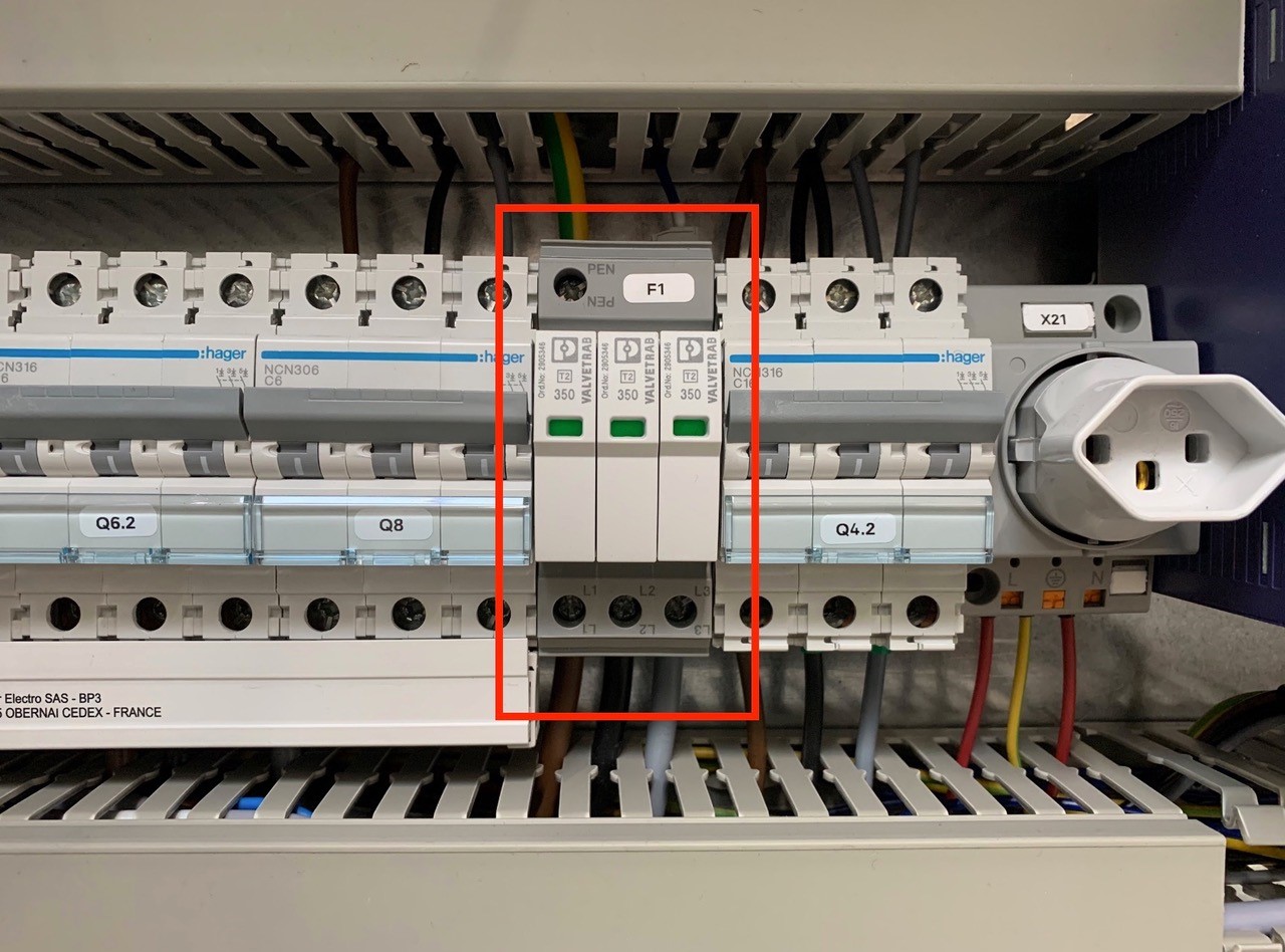
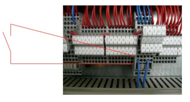
An overvoltage suppressor (or surge suppressor) is an appliance designed to protect electrical devices from voltage spikes. A surge suppressor attempts to regulate the voltage supplied to an electric device by either blocking or by shorting to ground voltages above a safe threshold.
These surge suppressors are built in to the latest Pacemaker models and machine controls (from 2009).
Check, if one or more modules of the surge suppressors are red/defect. Replace the red modules.
Attention!!!
Do not bridge the signalling contacts and run the machine with defective red modules because they no longer protect the system from voltage peaks!!!
If the modules are defective, check the main supply. Measure and check all voltages between the phases and all phases to earth before exchange the modules and restart the machine.
Possible cause:
Download PDF here
German instruction: page 52 – 55
English instruction: page 110 – 113
French instruction: page 172 – 175
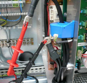
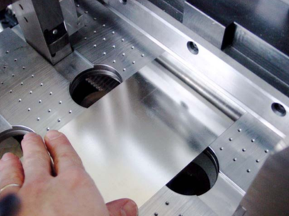
Use a common Ohmmeter, as you can see on the picture.
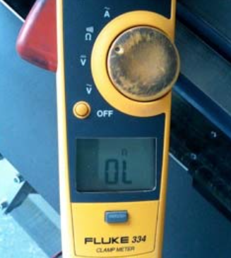
Measure the resistance between left carbide ring and main aluminum plate.
The measuring result on the Ohmmeter must be endless!
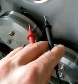
Measure the resistance between left carbide ring and main aluminum plate.
The measuring result on the Ohmmeter must be endless!
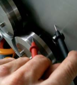
Measure between left and right carbide ring. The result on the Ohmmeter must be endless! This step is to ensure the proper insulation of both rear insulation rings around the taper roller bearings!
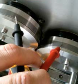
The picture shows the correct measuring result on the screen of the Ohmmeter for all three test points!
Download PDF here
Possible cause:
NOTE: There are two type of wire tension systems for the CM16:
Possible cause:
This is the result of a wrong flexer setting!
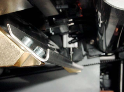
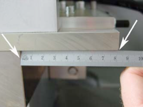
Open the rollformer and you undo the screw on the right handside of the “Flexer”. ![]()
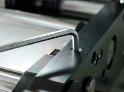
Measure with a ruler the actual position of the flexing wedge.
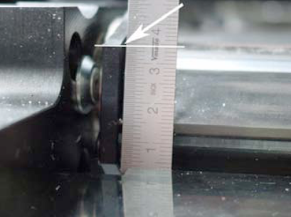
On the other side of the flexer, you can alter the position of flexer with the M8 screw. Choose a lower position for less flexing.
NOTE:
With more flexing the sheet comes out of the flexer station with less prebending.
If you do less flexing, means that the sheet comes out of the flexer station with more prebending.
NOTE:
After adjusting the flexer, you might have to adjust the rounding slighty!
For more information regarding the flexer and rollformer setting check our manual book 2 chapter 5.4.
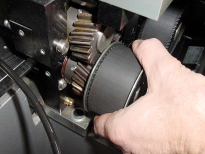
1 or 2 (sender/receiver) sensors are fitted behind the first pair of rollers to recognize double sheets.
Sensor in the lower part.
A pneumatic cylinder operates the ejection flap.
The double sheets detected by the sensor are diverted into this channel by means of a switch point.
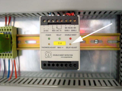
Setting the double sheet sensor
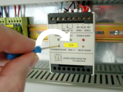
B30
The evaluation unit for the double sheet sensor is located in either the control box (illustration) or in the immediate vicinity of the rollformer, on the feeder side.
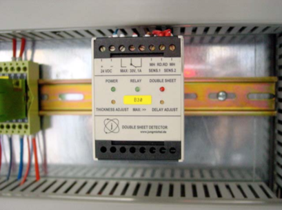
To set the sheet thickness, take a single sheet and lay it on the support rails in front of the first roller pair. You can also open the roll- former and lay a sheet into the rear area by hand. Then close the rollformer again.
Now turn the single sheet back and forward in the first roller pair by hand with the help of the belt.
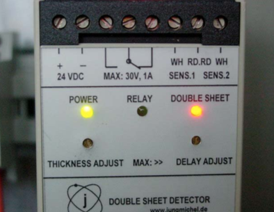
The two green LEDs „Power“ and „Relay“ should now be lit up on the evaluation unit.
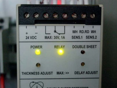
If the red LED „Double sheet“ is lit up, you must carry out a correction.
Turn the left-hand screw „Thickness Adjust“ clockwise until the red LED goes out and the green LED „Relay“ lights up. Add 1-2 additional turns in the clockwise direction.
Now carry out the same procedure with two sheets (double sheet).
The red LED „Double sheet“ should now be lit up.
The cylinder should now also be activated. It will be reset again when the sheets are removed.
Do not turn the right-hand screw „Delay adjust“; this is used for the delay of the cylinder stroke.
NOTE:
You will find further details in Book 5 OEM manuals on the CD.
Possible cause:
Possible cause:
NOTE: Only applicable for the model X8-350!
Download PDF here
Possible cause:
Special settings:
Download PDF here
Download PDF here
Possible cause:
The damaged/bended corner is touching first the inner catch rail.
The inner catch rail looks like a hook and will be found underneath the lower rollformer shaft on the catch station.
By changing the horizontal level of the catch channel slightly, the roll-forming direction of the tin plate will be changed/affected, and the whole tin plate edge should touch the catch rail equally.
Report all steps, new or different settings, and old and new production parameters (can size, cpm, weld speed, weld current, weld frequency, current wave-form and transformer step) for an easier overview and follow-up ! (www.canman.ch /Open new ticket and add your document)
Note on which tin-plate parameters (thickness, hardness, tin coating inside / outside, rolling direction, BA or CA, supplier, printed or not) such faults occur, and on which tin-plates not !
Basic parameters & settings to be checked first
Checklist to Avoid Micro Leaks
Micro leaks can occur within the seam and beside the seam – especially on cold-formed areas like necking, beading, flanging or seaming -, even if all above mentioned basic parameters & settings seems to be correct.
Micro leaks can have various sources: Wrong settings on the welder, tin-plate parameters which support such faults, worn or wrong machineries in the downline, or tin-plate parameters which do not fit to beader, necker, flanger and seamer.
For a better visual understanding put the faulty-can bodies in a water bath, and inspect the leaking area by a microscope. Store the pictures if possible!
Checklist to Avoid Flange-Cracks
Flange cracks can occur at the beginning and the end of the seam, even if all above mentioned basic parameters & settings seems to be correct.
Flange cracks can have various sources: Wrong settings on the welder, tin-plate parameters – for instant parallel rolling direction – which support such faults, worn or wrong flanger in the downline, or tin-plate parameters which do not fit to the flanger and or seamer.
For a better visual understanding put the faulty-can bodies in a water bath, and inspect the leaking area by a microscope. Store the pictures if possible!
We recommend following maintenance procedures:
Order numbers:
Safety data sheets see below:
The error occures when there is a problem with the measurement of the wire speed (not wire speed by self).
If there is still a problem with the measurement of wire speed, you can proceed as follows to restart production:
Please note: The workaround described above is not recommended for permanent production!
P03 = positioning countering error
Possible causes:
Possible cause:
Possible cause/checklist:
The recipe helps to adapt the speed of the incoming can into welding roller and the actual welding speed. In the best case, those speeds are equal.
Below you find a table of this recipe in steps of 10 mm can height.

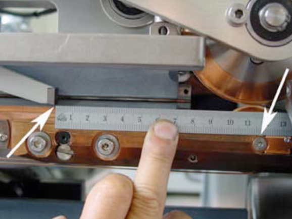
Turn the wheel of the synchrostar, that the pusher finger is as close as possible to the welding roll.
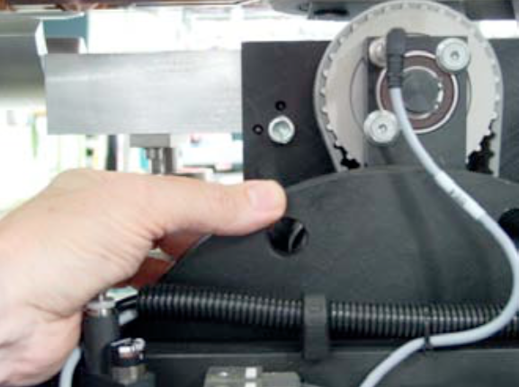
Measure now the distance from the top of the pusher finger to the center of the welding roll.
Distance = Can height – Overtravel Example:
Canheight: 122mm Overtravel: 4.8 mm
Distance: 117.2 mm
Possible cause:
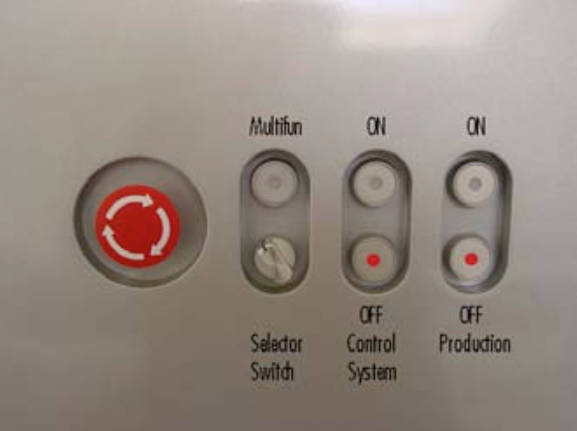
This problem occurs, if the main switch of machine is turned on, but the machine is not running production for a longer period. The cooling plate of servo drive is heating up, because the water valve is turned off during this time, to prevent condensation water.
Turn off the main switch, if you don’t run the machine for a longer time.
To get rid off the error with overtemp. servo drives you can go to the „Tuning page“. Press the button to switch on the main valve for the cooling system manually. Keep this button pressed for a few minutes, the system will cool down and you can start the machine normally. If you close the “Tuning page”, the main valve is switching back to automatic mode, controlled by „Production ON/OFF“.
Possible cause:
Possible cause:
Possible cause:
Maintenance, cleaning and insulation check (can be used in general for any welder)
Procedure:
Tubes have to be insulated in the area of rollformer, to avoid any contact to the ground.
(In the area of the lower welding arm is a simple insulation not possible).
− Take off the grounding cable from the lower copper plate going to the welding transformer
(Do not forget to place back after you finish).
− Clean the whole secondary circuit as good as possible by rag and compressed air.
Blow from rollformer side towards overhead exit conveyor, to protect the bearings in the rollformer.
− Mount the Z-bar back into the arm and measure the insulation by Ohm-meter > 10 Mega Ohm!
insulation plates).
− Check also every bearing. Attention: Most of them have ceramic balls, marked by a red point!
Make sure you are using only stainless steel screws and washers and lubricate the threads again!
Possible cause:
Possible cause:
Possible cause /checklist:
Possible causes:
How to reset:
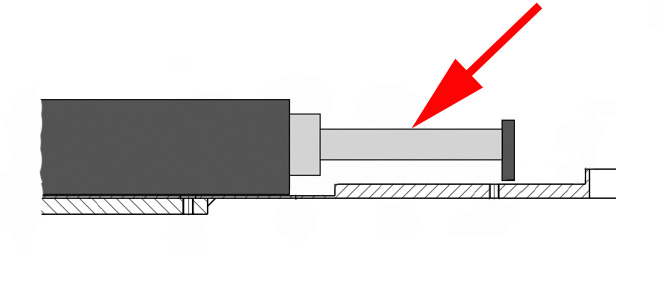
The recipe helps to adapt the speed of the incoming can into welding roller and the actual welding speed. In the best case, those speeds are equal.
Below you find a table of this recipe in steps of 10 mm in can height.
Turn the wheel of the synchrostar, so that the pusher finger is as close to the welding roll as possible .
Now measure the distance from the top of the pusher finger to the center of the welding roll.
Distance = Can height – Overtravel
Example:
Can-height: 122 mm, Over-travel: 4.8 mm
Distance: 117.2 mm
The position of the welding roll (WR) has an influence on the overlap at the beginning and at the end.
| WR slightly too high | = Overlap at the beginning less |
| WR slightly too low | = Overlap at the beginning constant |
| WR higher | = Overlap at the end better |
| WR lower | = Overlap at the end less |
| WR lower | = Overlap at the beginning less |
If you still couldn’t resolve the problem, read more at: I have problems to keep a constant overlap
Air Maintenance Unit
Oil:
Aral Vitam XR 46
(Festo – Part No. 12009388 T116)
Vacuum Pump
Mineral Vacuum Pump Oil
Multi Lube 100 – 750212 (Rietschle)
CM Article No. 003634 (5-lt container)
Cooling Unit
Coolant lubricant Zubora 92 F (standard)
CM Article No. 002609 (20-lt container)
PowerRoll™ Coolant H1 (food grade)
CM Article No. 011494 (7-lt container)
Gearbox
CLP 460 Oil
(e.g. Shell Omala 460)
See also data sheet on CD-Rom in Book 5
Central Lubrication Unit
Lithium Complex KP2P-30/EP – DIN 51502
NLGI Class 2 – Application –30 to +150°C
CM Article No. 007857 standard (400g)
CM Article No. 007858 food grade (400g)
Safety Data Sheet Cooling Lubricant
NOTE:
The safety data sheet of cooling lubricant you will find on CD-Rom in Book 5 in file „Cooling unit“
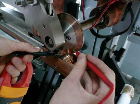
The center of the calibration crown (tooling) should be X = 2 – 3 mm behind the center of the pendulum roller head.

To adjust the position, tip the „tool out“ symbol. ![]()
Then you have to loosen the two M10 screws on top of the tooling plate.
Then you loosen the M6 counternut (1) below the plate, then you can adjust the position with the M6 screw (2). When you turn clockwise, you will reduce the distance, when you turn counterclockwise you increase the distance between the calibration crown and the pendulum roller head.
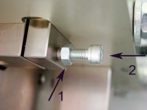
Tighten the counternut (1) again and then tip „tool in“ to check the position. ![]()
The correct setting!
An alternative spot to measure the correct distance is below the tooling plate:
X = 82 – 83 mm.
Remote maintenance:
In the electrical cabinet a modem with a remote maintenance adapter is integrated. Therefore you can do small changes over the phone line.

Recommended is an analog phone line with a direct phone number, with no internal connection through a switch board.

CAUTION:
Disconnect the phone line, if not in service! The remote maintenance system depends on a very good quality phone network. A bad network will make the service impossible.
NOTE:
There are two possibilities to do maintenance work or updates to the PLC Software.
Remote maintenance:
In the electrical cabinet a modem with a remote maintenance adapter is integrated. Therefore you can do small changes over the phone line.
Recommended is an analog phone line with a direct phone number, with no internal connection through a switch board.
CAUTION:
Disconnect the phone line, if not in service! The remote maintenance system depends on a very good quality phone network. A bad network will make the service impossible.
PLC Software Siemens Step 7:
The Siemens PLC is programed by the Siemens PLC Software Step 7TM, the panel (Touchscreen) by WinCC flexibleTM.

The following requirements are necessary to provide this service:
– Notebook with Software Step 7TM and
WinCC flexibleTM from Siemens
– MPI/DP (Profibus) interface
– Technical engineer with the software
knowlegde of Step 7TM + WinCC flexibleTM.
CAUTION:
If you change the software without prior consultation of CAN MAN, the works guarantee becomes void.
Possible causes:
Possible causes:
Possible causes/checklist:
Possible causes:
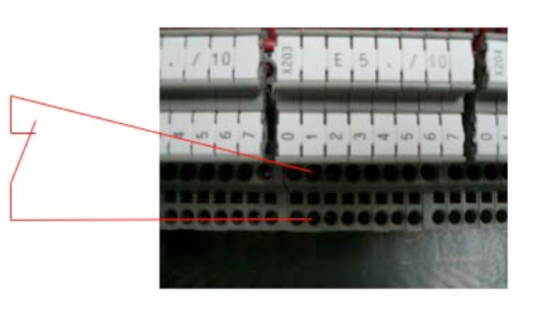
The instructions below show you how to connect the following signals: a) Line control b) Error powder unit and c) Release powder
Signal: line control
In order to switch off the downline due to an error, the PLC has a prepared input. To use this input, we need a potential-free signal from the downline, which is closed when the line is ready. Use the terminal E5.1 to connect the line control.
As soon as an error occurs, the destacking of the sheets stops and after an adjustable delay the wire-run and the remaining drives. The canbody transport continues to run slowly. This mode plus the flashing of the key „Production ON“ shows the operator the status of the line stop.
ATTENTION:
Machine begins to produce independently again, respectively after the release of the line control.
This input should be connected the same way as the line control. Here as well we need a potential-free relay contact of the powder unit. But this contact needs to be open, if there is any error. This signal needs to be connected to E126.7.
The production shuts off, if an error occurs. After that the operator needs to switch on the machine.
Signal: Release powder
In order to switch on the powder, we provide a change-over contact. The contact switches as soon as the production or a single can is triggered. In order to provide enough time for the initialization of the powder, the destacking is delayed by an adjustable time. Before you connect this signal, you have to remove the comb bridge (1) and the link (2), in order to make the contact potential-free.
Use the terminal K6.2 (A124.2).
NOTE:
Consult the electrical scheme of your welder to double-check the various input signals. In case you are not successful with the connection, contact a CAN MAN electrician.
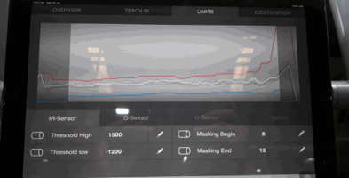
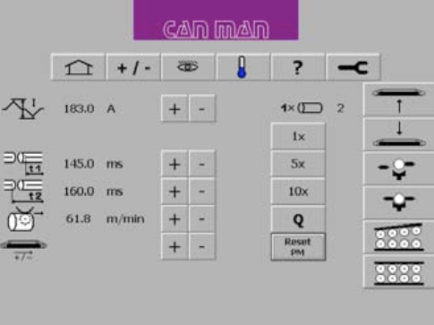
Cause 1:
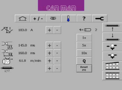
The setting of t1 and t2 is wrong. If the timing is wrong the PM cannot execute the signal, which is necessary to memorize the canbodies in the reject unit and to start the record of the graph.
Setting of t1 and t2:
t1 defines the starting point for the reduced current time window. ![]()
t2 is the time, where the reduced current windows ends. t2–t1= thus is the timespan for the reduced current, therefore t2 > t1! ![]()
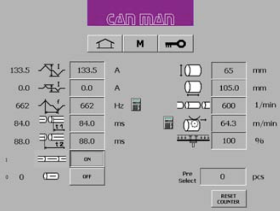
NOTE:
The value of t2 and t1 needs to be smaller as the cycle of one single can.
For example:
A production of 300/min. corresponds to a cycle time of 200 ms/can. Production of 600/min. corresponds to 100ms/can.
NOTE:
For a more detailed explanation of timing t1 and t2, consult your manual book 2, chapter 5.6.5. “Setting of Parameter t1 & t2 for reduced Current and Overlap Check“.
Cause 2:
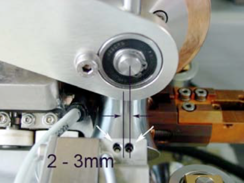
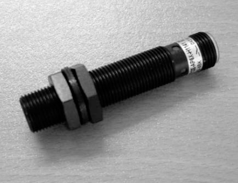
Check the inductive proximity switch B64 at the final pusher unit for function, operating distance and defect.
B64
Final pusher (Synchrostar II): Sensor B64.
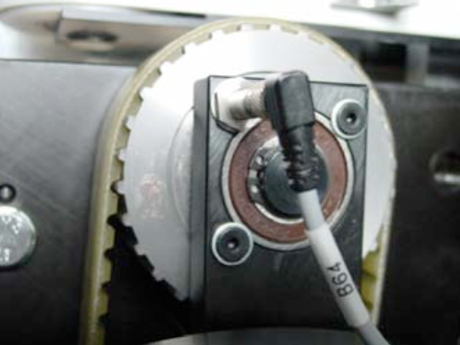
Description:
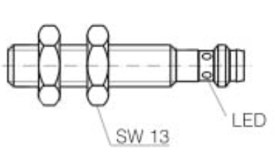
Inductive proximity sensor for embeddable mounting.
Polarity: PNP
Output: NO. or NC.
Operating distance: 2mm
Cause 3:
Check the tool switch B6 in the calibration tool for function, operating distance and defect.
B6
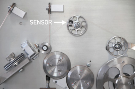
The position of the welding sensor B6, can be almost flush. Just make sure that you do not get scratches on the canbodies.
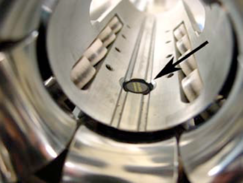
The height of the sensor can be adjusted here (see arrow).
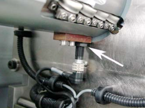
Inductive Sensor (magnetic field resistant)
Mounting mode: flush
Function principle: inductive/normally open Rated operating distance: 3 mm
Find a complete error list together with the interpretation of the error codes
Download PDF here
Possible causes:
NOTE:
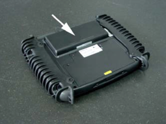
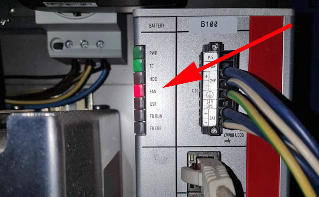
If you do not use the panel for a longer period (several weeks), the device should be turned off on the backside. Otherwise the internal battery will discharge and will get damaged!
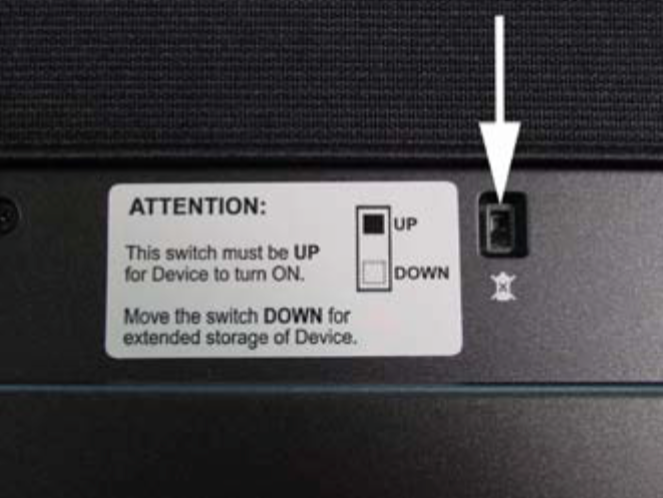
If you push the button on the right side, you are able to see the status of the integrated battery and optional available second battery.
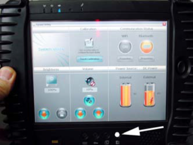
The optional second battery is located at the back of the device.