Problem:
Circuit breaker Q5 trips when the machine is switched on or during production.
Possible Causes or Resolutions:
Problem:
All drives are starting correctly, but the vacuum and welding current are not active.
Possible Causes & Resolutions:
Problem:
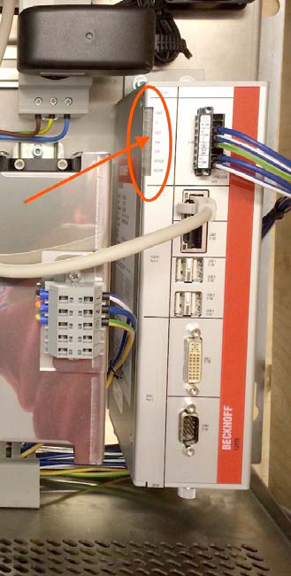
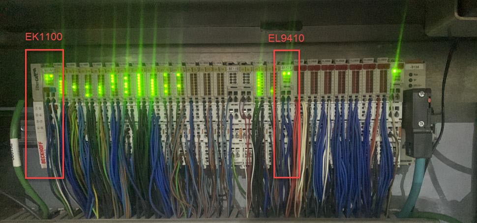
Some Beckhoff i/o terminals are not active and status LEDs are off, control does not respond to commands.
Possible Causes & Resolutions:
Problem:
After main switch off and on again, HMI piece counter values and settings are lost or old recipes are loaded.
Possible Causes & Resolutions:
Problem:
Machine stops and message „Pacemaker: Profibus communication error“ is displayed.
Possible Causes & Resolutions:
Problem:
The HMI cannot be started and the browser shows „NOT FOUND, The requested URL /en/default.htm was not found on this server“.
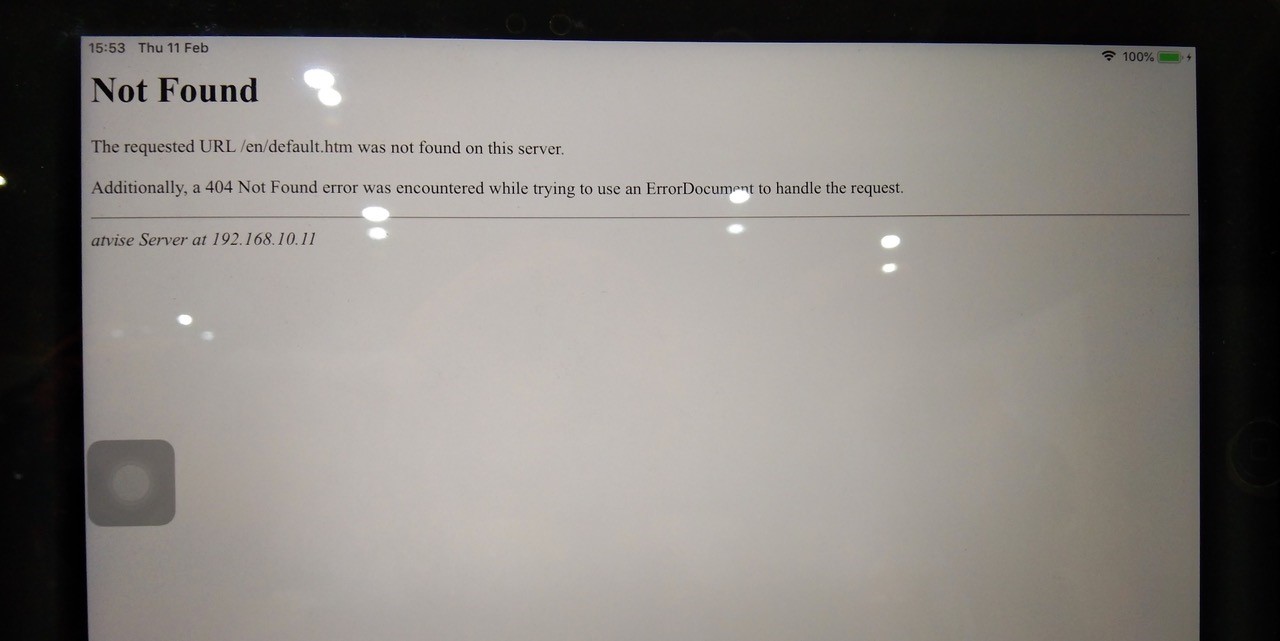
Possible Causes & Resolutions:
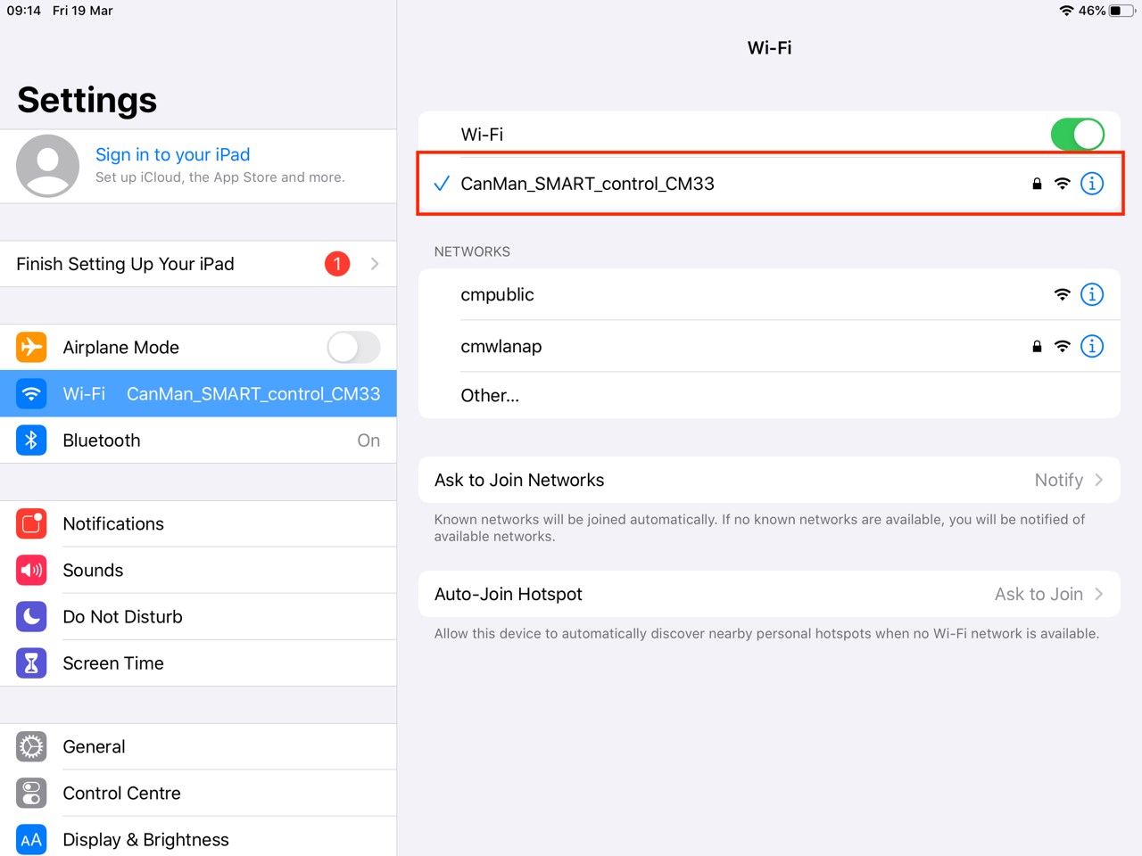
Not connected to Canman Wifi (only for wireless connected iPad’s): Check the wifi settings. Choose Canman wifi and try again.
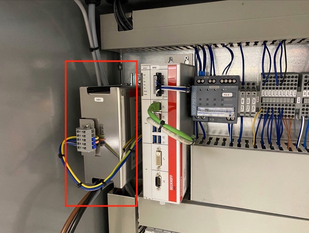
IPC has not shut down correctly: In this case probably the HMI software can’t start up automatically by restarting the machine.
Check the IPC after you switched off the main switch: Normally it will continue to run for at least 30 seconds to shut down correctly. If LED’s of IPC goes off within a few second, the battery of the UPS – unit is dead and needs to be replaced. Contact Canman for online support to restart HMI.
Note: If you use a new iPad the icons for the machine type can be produced, when you tap on “Add to home screen“ button.

Problem:
Display shows „Could not activate iPad“
Possible causes & resolutions:
For connecting an alternative display / PC, please have a look at the separate FAQ.
Please follow the below instructions carefully:
Take off the lower weld roll, unplug the grey water tube ø 10 mm labeled with “àWR” directly at the flow switch S26, and blow into the tube with air pressure. Check the out-going air-pressure at the free hole in the lower weld arm (supply for lower weld roll). If the circuit is free, you feel an equal air pressure (like on the output of the air gun) on your finger tip. If you recently took off the lower weld arm, there might be a problem with one or both o-ring seals between arm and upper bus bar:
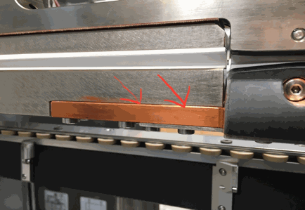
Please check them if needed !
Before re-connecting both grey tubes ø 10 mm, blow into one tube again by air-pressure, and feel the equal air-pressure on the other tube by your finger tip. If it’s ok, correctly connect both tubes again.
Battery of IPC is empty when:
To Do:
Click here for the status LED’s of the Beckhoff PC and how to access the PC in case of a trouble shooting.
Possible causes:
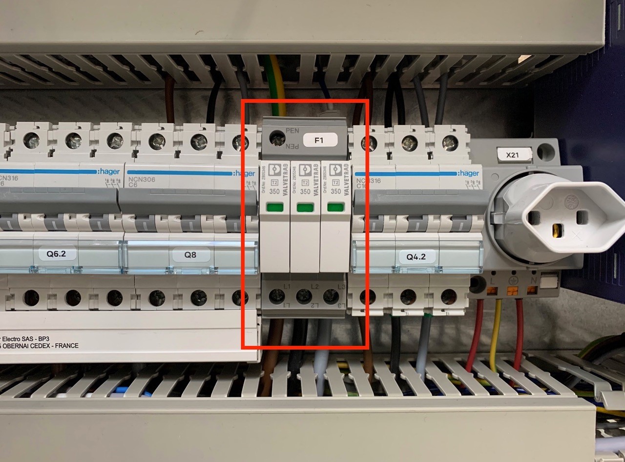
An overvoltage suppressor (or surge suppressor) is an appliance designed to protect electrical devices from voltage spikes. A surge suppressor attempts to regulate the voltage supplied to an electric device by either blocking or by shorting to ground voltages above a safe threshold.
These surge suppressors are built in to the latest Pacemaker models and machine controls (from 2009).
Check, if one or more modules of the surge suppressors are red/defect. Replace the red modules.
Attention!!!
Do not bridge the signalling contacts and run the machine with defective red modules because they no longer protect the system from voltage peaks!!!
If the modules are defective, check the main supply. Measure and check all voltages between the phases and all phases to earth before exchange the modules and restart the machine.
Possible cause:
Download PDF here
German instruction: page 52 – 55
English instruction: page 110 – 113
French instruction: page 172 – 175
Report all steps, new or different settings, and old and new production parameters (can size, cpm, weld speed, weld current, weld frequency, current wave-form and transformer step) for an easier overview and follow-up ! (www.canman.ch /Open new ticket and add your document)
Note on which tin-plate parameters (thickness, hardness, tin coating inside / outside, rolling direction, BA or CA, supplier, printed or not) such faults occur, and on which tin-plates not !
Basic parameters & settings to be checked first
Checklist to Avoid Micro Leaks
Micro leaks can occur within the seam and beside the seam – especially on cold-formed areas like necking, beading, flanging or seaming -, even if all above mentioned basic parameters & settings seems to be correct.
Micro leaks can have various sources: Wrong settings on the welder, tin-plate parameters which support such faults, worn or wrong machineries in the downline, or tin-plate parameters which do not fit to beader, necker, flanger and seamer.
For a better visual understanding put the faulty-can bodies in a water bath, and inspect the leaking area by a microscope. Store the pictures if possible!
Checklist to Avoid Flange-Cracks
Flange cracks can occur at the beginning and the end of the seam, even if all above mentioned basic parameters & settings seems to be correct.
Flange cracks can have various sources: Wrong settings on the welder, tin-plate parameters – for instant parallel rolling direction – which support such faults, worn or wrong flanger in the downline, or tin-plate parameters which do not fit to the flanger and or seamer.
For a better visual understanding put the faulty-can bodies in a water bath, and inspect the leaking area by a microscope. Store the pictures if possible!
We recommend following maintenance procedures:
Order numbers:
Safety data sheets see below:
Maintenance, cleaning and insulation check (can be used in general for any welder)
Procedure:
Tubes have to be insulated in the area of rollformer, to avoid any contact to the ground.
(In the area of the lower welding arm is a simple insulation not possible).
− Take off the grounding cable from the lower copper plate going to the welding transformer
(Do not forget to place back after you finish).
− Clean the whole secondary circuit as good as possible by rag and compressed air.
Blow from rollformer side towards overhead exit conveyor, to protect the bearings in the rollformer.
− Mount the Z-bar back into the arm and measure the insulation by Ohm-meter > 10 Mega Ohm!
insulation plates).
− Check also every bearing. Attention: Most of them have ceramic balls, marked by a red point!
Make sure you are using only stainless steel screws and washers and lubricate the threads again!