Please follow the below instructions carefully:
- Cooling unit for cold water (for both welding rollers):
- The cooling emulsion must be changed yearly, but more preferably every 6 months. Follow the X7 manual if you have to change the emulsion !
- The filter cartridge of 50 µm needs to be replaced monthly ! Follow the X7 manual if you have to the filter cartridge !
- Check the level of the cooling emulsion on the internal tank. If you have to refill the tank, follow the X7 manual to get the correct mixing ratio for the emulsion, and fill the tank. Note: If the water level is too low, the chiller should show an error message, and the X7 should stop and show an error on the iPad !
- Cooling water / emulsion distribution station on X7:
- Run some (5 to 10) can bodies and control the water pressure on the manometer: 5.0 bar is the min. required water pressure !
- Run some (5 to 10) can bodies and control the water flow on the flowmeter S26 (2. From right side): 5.0 liter per minute is the min. water flow.
- Note: The water pressure switch S120 is set to > 4.0 bar. If there is the error message “Error S120” on the iPad , first check the water pressure on the manometer, and if it’s below 4.0 bar check the cooling unit again !
- Weld roll ø 42 / 49 / 54 / 62 / 90 mm and lower weld arm:
- It’s possible that the cooling circuit from waterflow meter S26 to lower weld roll, and back to the outlet on the water distribution, is blocked:
Take off the lower weld roll, unplug the grey water tube ø 10 mm labeled with “àWR” directly at the flow switch S26, and blow into the tube with air pressure. Check the out-going air-pressure at the free hole in the lower weld arm (supply for lower weld roll). If the circuit is free, you feel an equal air pressure (like on the output of the air gun) on your finger tip. If you recently took off the lower weld arm, there might be a problem with one or both o-ring seals between arm and upper bus bar:
Please check them if needed !
- Now unplug the grey tube ø 10 labeled with “WR à” on the water distribution and blow into the tube with air pressure. Check the out-going air-pressure at the free hole in the lower weld arm (exit of lower weld roll). If the circuit is free, you feel an equal air pressure on your finger tip
- If you re-install the lower weld roll again, make sure that the arrow “running / turning direction” is showing into the right direction.
Before re-connecting both grey tubes ø 10 mm, blow into one tube again by air-pressure, and feel the equal air-pressure on the other tube by your finger tip. If it’s ok, correctly connect both tubes again.
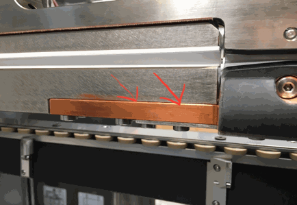
- Copper wire / copper wire profiling unit:
- Measure the copper wire profile after the profiling unit on various positions (within around 300 mm). Check the correct width in the X7 manual. The tolerance must be within 0.03 mm !
- Please check if the wire guiding wheel in front of the lower weld roll is broken. If it’s broken, replace it by a new one. Make sure you choose the correct size 1.90 or 2.30 mm !
- Please check if the copper wire tension is correct. Set the correct tension according X7 manual !
- Welding parameters:
- Please check the weld pressure. Set the correct welding pressure according X7 manual. The range should be between 40 and 50 daN.
- Please check the welding frequency. Set the correct value according the recommendation in the iPad !
- Please check the welding overlap. The welded overlap should be nosepiece overlap + 0.1 mm !
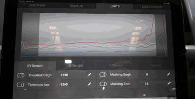
- Check if the IR-Sensor graph of the Qualimaker 2™ on the iPad are within the correct range and straight, which means that the crown and exit conveyor settings are correct:
- Other possible errors:
- If the copper wire gets burned, check if the upper and lower weld roll are touching each other without a blank between. Press the button on the main-aluminium plate to close the welding roller and test it.
