Possible causes:
This is the result of a wrong flexer setting!
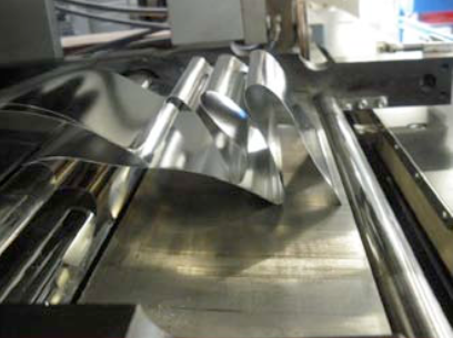
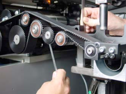
Open the rollformer and you undo the screw on the right handside of the “Flexer”. ![]()
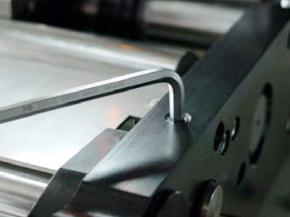
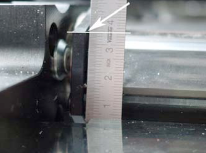
Measure with a ruler the actual position of the flexing wedge.
On the other side of the flexer, you can alter the position of flexer with the M8 screw. Choose a lower position for less flexing.
NOTE:
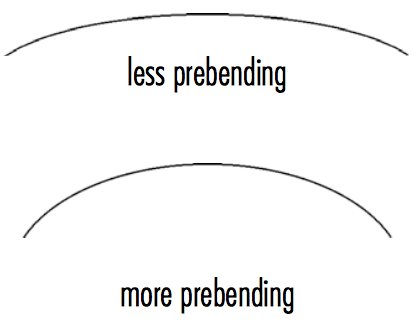
With more flexing the sheet comes out of the flexer station with less prebending.
If you do less flexing, means that the sheet comes out of the flexer station with more prebending.
NOTE:
After adjusting the flexer, you might have to adjust the rounding slighty!
For more information regarding the flexer and rollformer setting check our manual book 2 chapter 5.4.
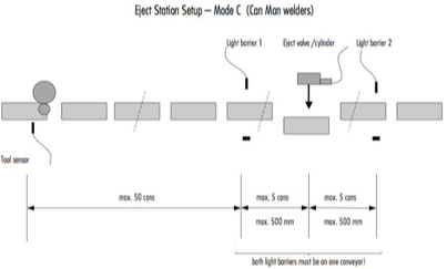
Possible Cause (CM16 / S, X8):
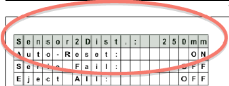
Adjustment of the light barrier distance to eject cylinder might be wrong.
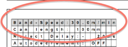
Wrong adjustment of the transport belt speed.
NOTE:
The ejected can should whether touch the can before nor the following.
Eject pulse cylinder has to fit to production speed:
Recommendation: 150-200msfor<100cpm 100-150msfor100-200cpm
80-100msfor200-400cpm
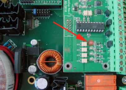
Place a canbody between the second light barrier and check the LED „LD3“ on the eject print (inside the Pacemaker).
Must be „ON“.
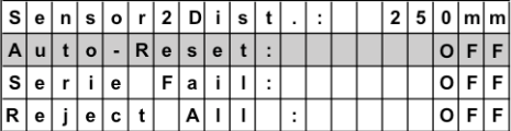
The autoreset needs to be “OFF”. Therefore the can memory will not be reset automatically.
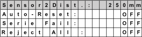
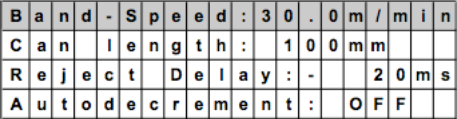
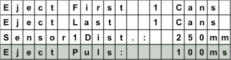
Check, if your hardware parameters are set correctly, according to one of the three layouts.
=> See layouts below!
Possible Cause (Pacemaker):
P03 = positioning countering error
Possible causes: