Support

7 Support Entries

Problem:

Canbody transport motor doesn’t move correctly to the reference position, or stops, or changes the direction of rotation, or the display of the servo controller U7 shows „IMax“ or „P03 trip“.

Possible Causes & Resolutions:

To check:

  • Mechanical condition of canbody transport motor: Turn it by hand and check that everything runs smoothly.
  • Resolver mounting: Is firmly connected to the motor shaft?
  • Resolver bearings: Remove the resolver from the motor shaft and check if it is turning smoothly.
  • Resolver and motor connections: Motor and resolver are connected correctly and clamps/plugs tightened?
  • Motor windings: Disconnect the motor from the inverter and check the windings with an ohm meter (U-V,U-W,V-W). All values are equal?
  • Output servo controller: Measure the inverter output voltage when it should run (U-V,U-W,V-W). If 0V and display shows „IMax“ maybe servo controller defective.


  • Machines with lift table and non-stop: Check whether the white gear wheel on the encoder shaft of the downstacker motor is fixed on the shaft by the M3 grub screw. Make sure that the grub screw is aligned to the flat surface on the shaft.

Possible causes:

  • Check the blank cutting tolerances and blank squareness.
  • Adjust the rollformer (roller shaft clearance and spring pressure) according to the manual.
  • Control if there is a high difference in the tin plate hardness, by rollforming 10 bodies without welding. Put them on the floor in line and compare the difference in the rollforming overlap.
  • Check if the destacking process is going well. Make sure the tin plate is guided tight, and the separating air is positioned well.
  • Control the timing of the tin plate transport in between two transport fingers.
  • Make sure that the guidance channel is properly adjusted. The intersection to the precalibration of the calibration crown is most important.
  • Check the position of each (inside and outside!) transport finger compared to rollformed canbody.
  • Check the offset of each finger pair itself. Move the canbody slowly forward (X1 and X6 by slow mode function) and observe eventual shaking of the canbody until the welding point.
  • If a third finger exists: The third finger must be 0.5 mm behind the upper main pusher fingers!
  • Reset the calibration crown completely. Make sure that each precalibration roller is turning easily! If needed lubricate their shafts slightly and clean the roller afterwards. Make sure that these rollers are as close as possible to each other!
  • Measure the speed of the flat belt in the calibration crown:
    The speed must be absolutely identical with the copper wire speed!
  • Measure the overtravel: Short can heights shall have 1 mm overtravel.
  • The center of the diabolo roller (equal to the center of calibration crown) shall be 1–2 mm before the welding center.

Replace the belt dogs:
Turn the polygon shaft until the belt dog is easy accessable from side of the machine.


Loose the two screws on each belt dog.


Then replace the belt dogs, be careful that belt dog, is correctly placed in the timing belt, as shown in the picture.


NOTE:
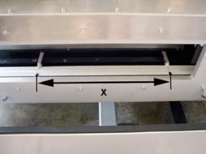
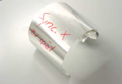
If you need to place the belt dogs, in a new location, due to a damaged belt area, make sure that the distance x is always the same around the entire belt loop.
Also make sure that inside and outside belt dogs are corresponding to each other!

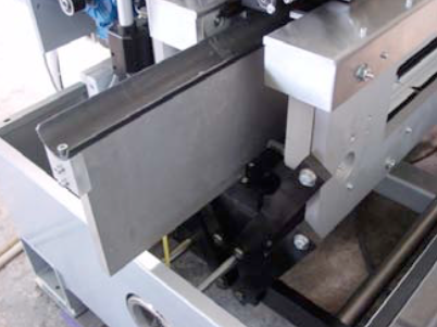
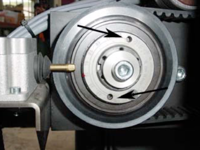
Exchange the body transport belt


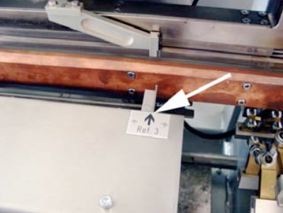
Turn the polygon shaft until a belt dog is inline with reference 3.


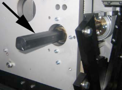
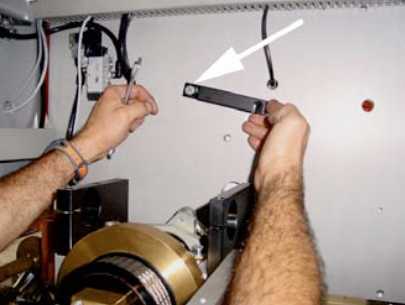
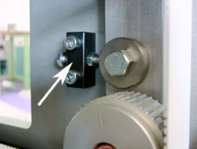
Take off the bracket (see picture),in the back of the front plate.


Then mount the screw loosely to side plate of the synchrostar unit.


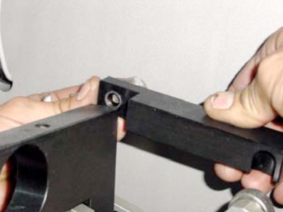
Slide the slot of the bracket around the crank handle and tighten the screw.


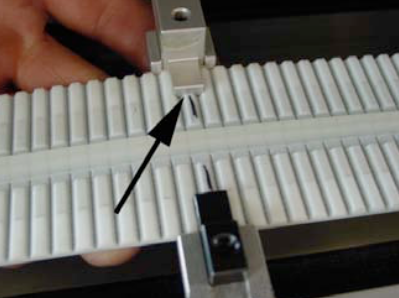
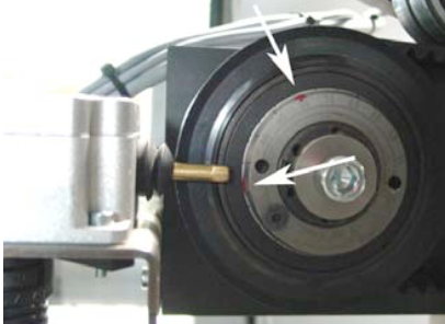
Now you have to release the tension of the synchrostar belt, by loosing the M12 screw.


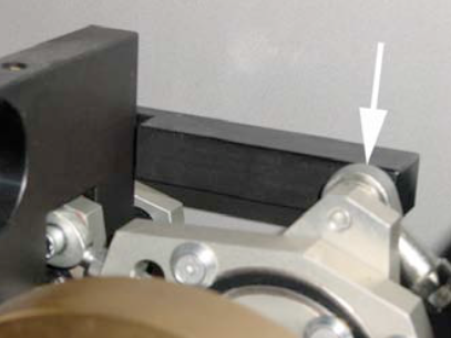
Then release the tension of the body transport belts. The white arrow shows you where you can release the tension of the outside belt. The inner belt has the same feature.


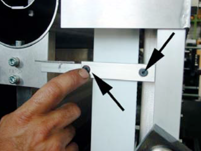
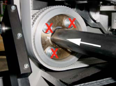
Untighten the two set screws.


Loose sligthly the three M8 screws (1) first, then undo the M8 screw sligthly too (2). Now you can release the clamping force by turning the M8 nut (3) a little bit.


Now, you should be able to move shaft to the front of the machine and to replace both body transport belts.
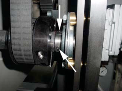
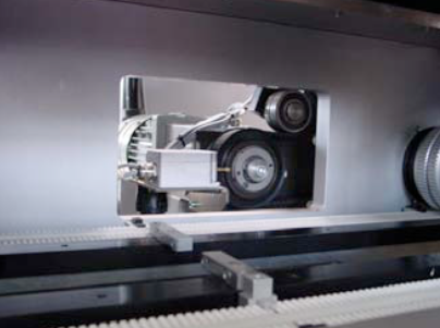
NOTE:
Do not loose any other screws, as for example the red marked ones in the picture.


After you have replaced the body transport belts, follow the above instruction in the reverse sequence.
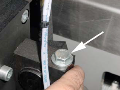
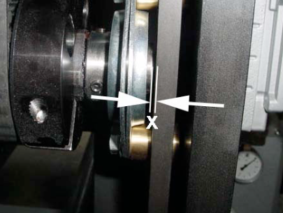
NOTE:
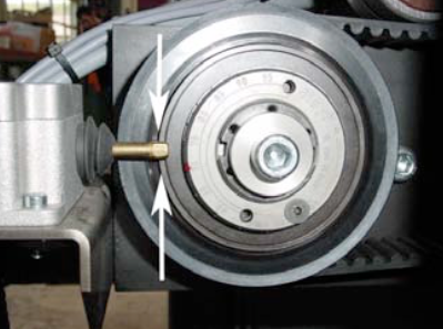
When you push back the polygon shaft and clamp it, make sure that you keep a clearance of x=1mm as shown in the picture.

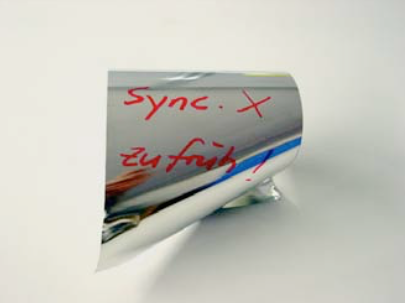
This is a sample, where the synchronsation is too early. The blank hit the finger/dog of the body transport.


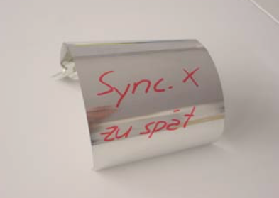
Here the synchronsation is too late. The blank came in alright, but the finger/dog came too early to do the start the transport.


Here a different angle of the damaged blank (late synchronisation).


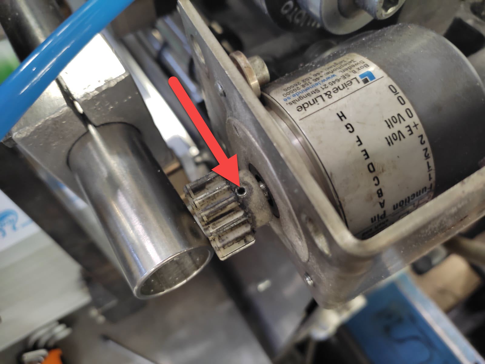
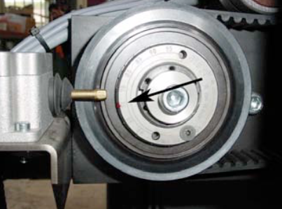
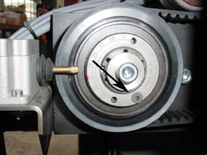
How is the distance between the clutchring and the switch?
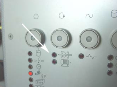
Trigger the clutch by hand and check if the red LED light comes on.


This is the LED, which should light up.


Try if you can hold the polygon shaft by hand tightly and trigger the clutch and therefore an immediate machine stop.


If you need to alter the torque of the clutch, do the following:


Loose both black screws of the guiding channel.


Pull the channel to the back of the machine.


Now you can see the clutch.


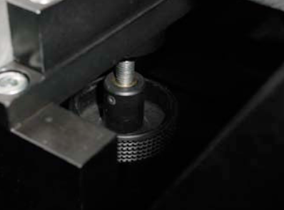
The basic setting should be 70 NM – see the red mark.


Loose the countersunk screw and take the screw out.


Turn the clutch clockwise with a special tool or a drift punch and a plastic hammer.


You can reduce or increase the torque by steps off 5 Nm, in order to fit the countersunk screw in.
(Picture shows a reduction to 50 Nm)


Now push back the channel back into the machine and tighten the black screws.

For further information find the Mayr clutch manual here:

Mayr EAS 450

Mayr Smartic 0-481-325

  • Check first whether the conveyor / elevator unit is blocked somewhere!
  • Check the 24 VDC fuse according electrical diagram. Make sure that the correct size will be used!
  • Check the setting of the respective sensor (according electrical diagram), which allows the conveyor to move if the sensor is active / free!
  • Take the 24 VDC motor out, and check whether the motor is defective or not! Make sure that the conveyor is not moving downwards as soon as the mechanical connection between motor and elevator unit has been released!

Possible cause:

  • Check the air pressure on the small air regulator, the value must be around 0.5bar (pressure to engage the clutch).
    • refer also to the touch screen “Air” symbol, where you find the exact values.
  • Check the air pressure on the precision air regulator, left side from synchrostar motor, to 1.6 to 2.0 bar (pressure to disengage the clutch)
    • refer again to the touch screen “Air” symbol.
  • Check whether the safety clutch is engaged or not: Turn the synchrostar by hand, and see whether the motor is also turning or not. If yes, the clutch is engaged!
  • If the clutch is engaged, but the error message still remains, the sensor B69 might wrong positioned:
    • Check if the LED from the sensor is OFF.
    • If the LED is still ON, turn the sensor a quarter turn counterclockwise, or until the LED is OFF. Do not turn the sensor too much counterclockwise. If the distance is too big the clutch does not stop the machine in case of a crash. To test you can adjust the precision air regulator of clutch to „0“. Now the clutch is disengaged and the sensor has to be ON.
    • Make sure that the sensor has still a clearance of about 0.5mm refer to manual Mayr EAS 450  or Mayr Clutch 0-481-325
    • Turn the synchrostar and make sure that there is no resistance coming from the sensor/clutch!
All Can Man content is now also available on the Soudronic Group website.
Where do you want to continue your journey?
All Can Man content is now also available on the Soudronic Group website.
Where do you want to continue your journey?