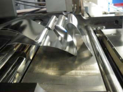
This is the result of a wrong flexer setting!
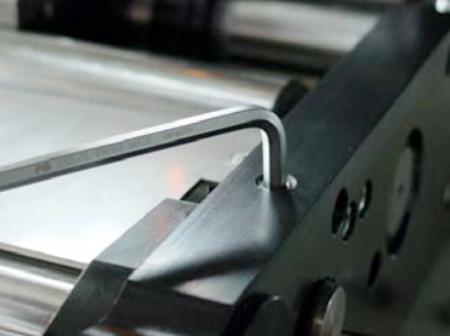
Open the rollformer and you undo the screw on the right handside of the “Flexer”. ![]()
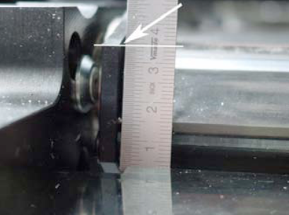
Measure with a ruler the actual position of the flexing wedge.
On the other side of the flexer, you can alter the position of flexer with the M8 screw. Choose a lower position for less flexing.
NOTE:
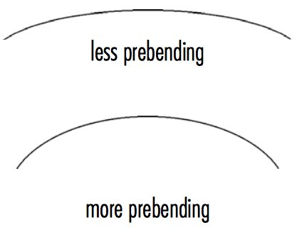
With more flexing the sheet comes out of the flexer station with less prebending.
If you do less flexing, means that the sheet comes out of the flexer station with more prebending.
NOTE:
After adjusting the flexer, you might have to adjust the rounding slighty!
For more information regarding the flexer and rollformer setting check our manual book 2 chapter 5.4.
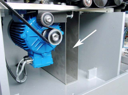
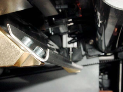
1 or 2 (sender/receiver) sensors are fitted behind the first pair of rollers to recognize double sheets.
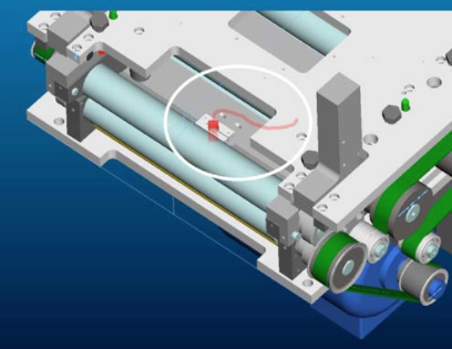
Sensor in the lower part.
A pneumatic cylinder operates the ejection flap.
The double sheets detected by the sensor are diverted into this channel by means of a switch point.
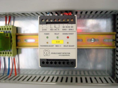
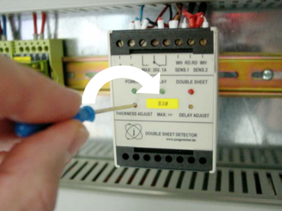
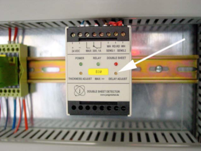
Setting the double sheet sensor
B30
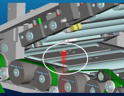
The evaluation unit for the double sheet sensor is located in either the control box (illustration) or in the immediate vicinity of the rollformer, on the feeder side.
To set the sheet thickness, take a single sheet and lay it on the support rails in front of the first roller pair. You can also open the roll- former and lay a sheet into the rear area by hand. Then close the rollformer again.
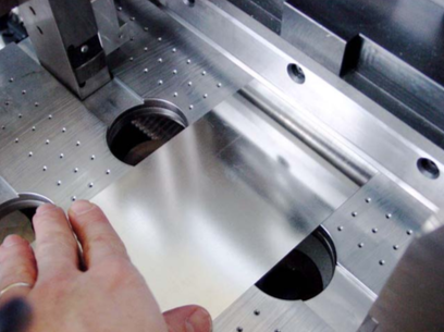
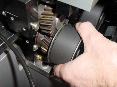
Now turn the single sheet back and forward in the first roller pair by hand with the help of the belt.
The two green LEDs „Power“ and „Relay“ should now be lit up on the evaluation unit.
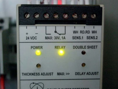
If the red LED „Double sheet“ is lit up, you must carry out a correction.
Turn the left-hand screw „Thickness Adjust“ clockwise until the red LED goes out and the green LED „Relay“ lights up. Add 1-2 additional turns in the clockwise direction.
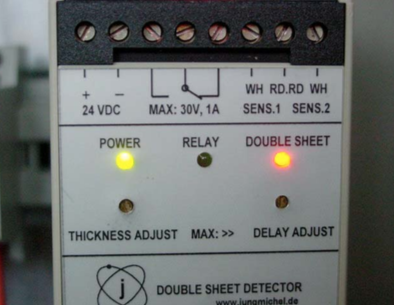
Now carry out the same procedure with two sheets (double sheet).
The red LED „Double sheet“ should now be lit up.
The cylinder should now also be activated. It will be reset again when the sheets are removed.
Do not turn the right-hand screw „Delay adjust“; this is used for the delay of the cylinder stroke.
NOTE:
You will find further details in Book 5 OEM manuals on the CD.
Possible cause:
