Possible cause:
Corrective measure:
Possible cause:
Corrective:
Cause:
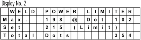
The actual value of the weld power limiter increases with the heating of the machine.
Corretive:
Readjust the weld power limiter, to a higher value. Observe the “Max” value from a “cold “ start to a “warm up” machine during production. See also note below.
NOTE:
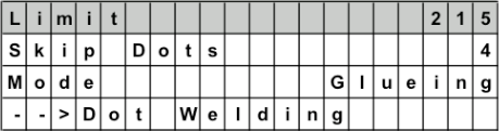
Power limit to activate the weld guard (stitch welding). Normally 5 – 10 % more than the actual “Max” value during production.
0 = Weld Power Limiter Off !
Problem:
The display shows the set current value, but the duty cycle is very low or 0%!
Possible cause:
DO NOT ATTEMPT TO SWITCH “ON” THE CURRENT ANYMORE!
Further attempts to switch on the current, can destroy or damage the semiconductors (IGBT) in the Pacemaker!
Using a handpanel:
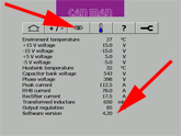
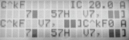
When you start up your Pacemaker, the software version will be displayed during the boot process.
Alternatively the information will we displayed, when you press the key “down” several times until you get to “Info Version”: e.g. 5.27
Using a CM16 welder you will also find the info by pressing the key “down”, since the display is the same as the handpanel of a PM.
Using a X1 welder:
Tip on the *eye” icon and the Pacemaker software version is displayed on the bottom line.
Using X8 welder:
Tip on the “eye” icon and then on a second “eye” icon to get to software version info on the bottom line – check also your manual book 1 – chapter 4.6. how to find the info.
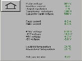
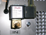
Scroll down in the display menu until you reach the temperature display. Observe, if after crossing the switching threshold, the temperature doesn’t change, that the solenoid valve is blocked (when the 2nd thresholds are reached the message “over- or undertemperature” will be displayed).
NOTE: The error message “Ths too low (Ths = Temperature Heatsink)” might be an indication for a contaminated valve.
The Pacemaker has the following options to connect the output of the weld power limiter to other systems/controls (i.e. can rejection control):
If you have connect the control panel and you can see only strange signs in the display, the connecting speed can be wrong. The Pacemaker control panel can run in two modes.
19200 baud
Control panel standard is 19200 baud (Used for connecting between control panel and PLC )
9600 baud
9600 baud (Used only for connecting between PLC and Pacemaker)
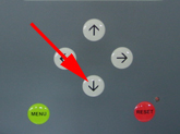
How you can change to 9600 baud:
Switch off the Pacemaker (Main switch off)
Press the “MENU” button while starting the panel. ![]()
Now the control panel runs with 9600 Baud Can Man machines with PLC.
How you can change to 19200 baud:
Switch off the Pacemaker (Main switch off)
Press the “RESET” button while starting the panel. ![]()
Now the control panel runs with 19200 baud
Control panel and PLC.
Possible Cause (CM16 / S, X8):
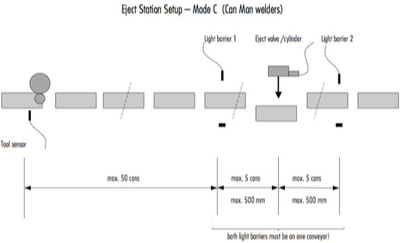
Adjustment of the light barrier distance to eject cylinder might be wrong.
Wrong adjustment of the transport belt speed.
NOTE:
The ejected can should whether touch the can before nor the following.
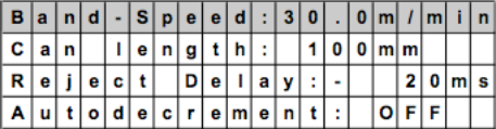
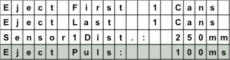
Eject pulse cylinder has to fit to production speed:
Recommendation: 150-200msfor<100cpm 100-150msfor100-200cpm
80-100msfor200-400cpm
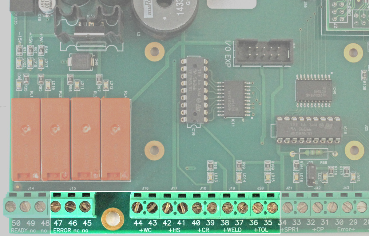
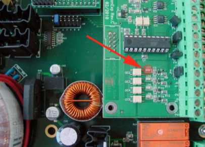
Place a canbody between the second light barrier and check the LED „LD3“ on the eject print (inside the Pacemaker).
Must be „ON“.
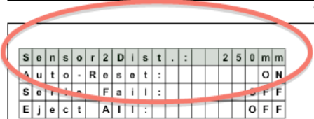
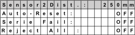
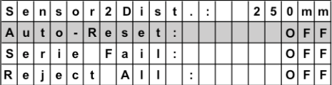
The autoreset needs to be “OFF”. Therefore the can memory will not be reset automatically.
Check, if your hardware parameters are set correctly, according to one of the three layouts.
=> See layouts below!
Possible Cause (Pacemaker):