Support

12 Support Entries

Possible cause:

  • Defective print.

Corrective measure:

  • Replace the small print for eject station.

Cause:

The actual value of the weld power limiter increases with the heating of the machine.


Corretive:

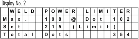
Readjust the weld power limiter, to a higher value. Observe the “Max” value from a “cold “ start to a “warm up” machine during production. See also note below.
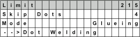
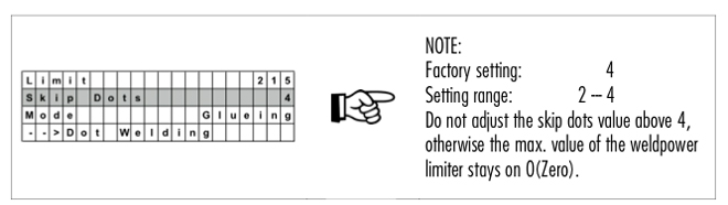

NOTE:

Power limit to activate the weld guard (stitch welding). Normally 5 – 10 % more than the actual “Max” value during production.
0 = Weld Power Limiter Off !


Problem:
The display shows the set current value, but the duty cycle is very low or 0%!

Possible cause:

  • Short circuit in the welding transformer!


DO NOT ATTEMPT TO SWITCH “ON” THE CURRENT ANYMORE!
Further attempts to switch on the current, can destroy or damage the semiconductors (IGBT) in the Pacemaker!

Important requirements:

  1. t2 must be always higher than t1 (t2 > t1).
  2. t2 and t1 must be set lower than 1 cycle time of the machine. For example, if the machine is running with 300 cans/min the cycle time is 200ms. Therefore, t2 and t1 must be set lower than 200ms.
  3. To do an overlap check set  “overlap check” to “ON”. The reduced current will be set automatically to 0A. In the same window you have an additional value. If you set this for example to 10ms you have more unwelded area at the beginning and end of can.
    NOTE: If you use “overlap check” function is not necessary to switch “Ired” to “ON”.


Possible problems, if the overlap function does not work!

  • If you can’t see the value t2 and t1, maybe the pacemaker is running with “Old” mode and not with “CMX” mode. Change in the setup “CT” from “Old” to “CMX”.
  • No input signal on input 4 (terminal 7 and 8 on pacemaker board). If machine is running, LED behind input 4 (clamp 7 and 8) must flashing. This is the cycle signal to start the timer t2 and t1 for the overlap check.

Possible cause:

  • Check your welder according checklist Conical overlap / micro leaks
  • If your Pacemaker is programed to weld with sine wave (check the IBS), we can change to triangle wave form.
    • Please contact us for further instructions.

Problem:

  • % going up to 100% after some seconds of welding
  • A current is dropping down after some seconds of welding
  • There is a low current of only a few amp’s
  • Current is dropping significantly down after some seconds of welding


Possible cause(s):

  • the welding roll might be defect
    • change welding roll
  • in case you use a mercury based welding roll
    • add some mercury
  • the pendulum roll might be defect
    • change the pendulum roll
  • in case you use a mercury based pendulum roll
    • add some mercury
  • the transformer step switch might be defect
    • change transformer step switch

NOTE: The reason for the low current is due to an open circuit. The wire might be also hot in this case. If you have in general a high power percentage you might reduce the frequency.

The Pacemaker has the following options to connect the output of the weld power limiter to other systems/controls (i.e. can rejection control):

  1. E-Relay
    E-Relay of Pacemaker does stop the welder if weld power limiter is active. To connect, use the clamp No. 45, 46 and 47 (potential free relay contact 47=>com, 46=>nc, 45=>no).
    To use this function, the parameter “Wld fault” in the Pacemaker settings has to be set to “E-Relay”. If weld power limiter is activated, the E-relay do switch on, welder stop and must be reset on the Pacemaker display before the welder can be restartet. Of course the operator has to check the last welded cans to make sure that no unwelded cans go to the downline.
  2. +Tol output (Clamp 35/36, 35=>0V, 36=>24Vdc)
    This output is switching on if the weld power limiter is active and can be used also to activate an ejector or other function. The next can will be welded normally and +Tol output will switch off automatically. If you want to use that output, you can change the parameter “Wld fault” to “nothing”. In this case, the E-relay will not be activated and the welder can run continuously without to stop if the weld power limiter detect a can. Of course you need an additional logic for the eject timing and eject the right can.
  3. +CR output (Clamp 39/40, 39=>0V, 40=>24Vdc)
    This output will be activated if the weld power limiter is active according to the parameter “WLD fault”. You can choose different settings like “CR39/40”, “CR 50ms”…
    Example: CR 50ms => Pulse of 50ms on CR output if weld power limiter detect a bad can.
  4. Can Man eject unit
    With this option it is possible to eject cans and also to eject the first and last can of a series. Please contact Can Man for an offer.Attention!!! +Tol and +CR output is supplied by the internal 24Vdc of the Pacemaker electronic board. This output is not potential free!!! Use a small 24Vdc relay to connect the signal with other systems/controls.The settings of beginning and end of can (T1/T2 or IT/ET) must be set correctly, also if you don’t use the IRED function. With this timing, the weld power do switch on the current for the next can after a stop in case of contamination (overlacquering).Code to enter the system setup: down, right, left, left, up, left, right, right

  1. Check if there is a higher trafo step
  2. Lower the freqency if possible
  3. Check machine insulations

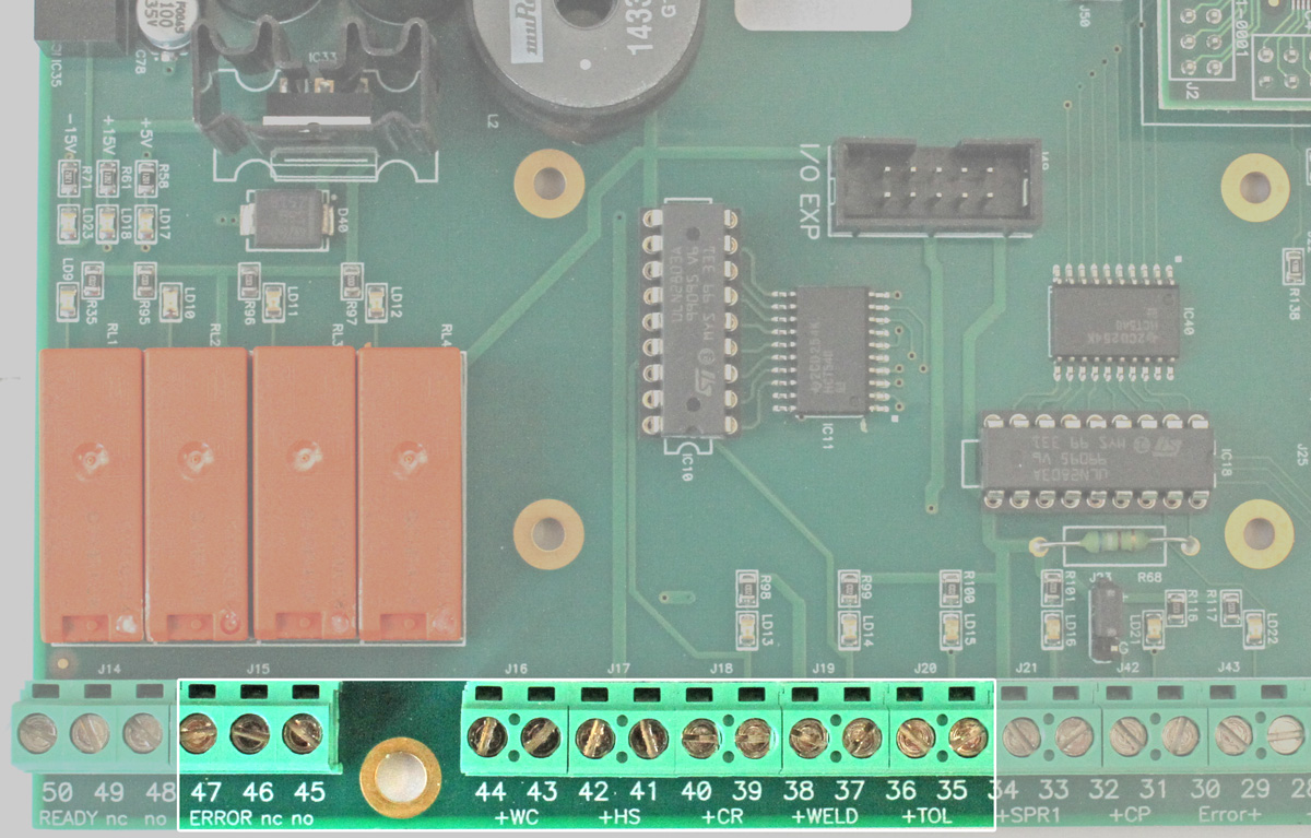
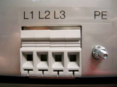
Check the main supply
R-380VAC (L1), S-380VAC (L2), T-380VAC (L3).


Check if all green LED’s are “ON”.


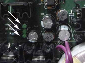
Check in the display of pacemaker the actual displayed voltage R, S and T! (old version PM)


If you can see these values and one of them looks to low, you can adjust it with the three small potentiometer on left side of processor board (old version PM).

  • Check sensor on tool
  • Check setting of t2 and t1
  • Check input of reduce current signal. LED of input 4 of pacemaker board.
  • Check the Max Gap setting. Factory setting 80%.
  • For testing you can set Max Gap to 0% => function off. Attention! No correction of the memory if cans are removed before the ejection station.
  • The message “jam in welding section” means the welding sensor B6 is on for 4 seconds without switching on and off. In normal production the sensor is switching on and off for each can.
    • Check the function of the sensor!

All Can Man content is now also available on the Soudronic Group website.
Where do you want to continue your journey?
All Can Man content is now also available on the Soudronic Group website.
Where do you want to continue your journey?