Support

11 Support Entries

Problem:

Circuit breaker Q5 trips when the machine is switched on or during production.

Possible Causes or Resolutions:

  • Measure voltages at all phases, even under load. It is possible that one phase did drop down, and this triggered the circuit breaker.
  • Measure the current of each phase with a current clamp after Q5. If the measured value is below the value of the circuit breaker and Q5 still keeps tripping, the circuit breaker may be defective. Replace it.
  • Maybe the parameter “Low bat voltage” (coming from Pacemaker) is set too low: That means that the contactor in the Pacemaker closes too early with a precharge voltage that is too low and therefore Q5 trips. To check this, please open a ticket to contact CanMan.

Problem:

Machine stops and message „Pacemaker: Profibus communication error“ is displayed.

Possible Causes & Resolutions:

  • Cooling water valve: Wrong type of valve or plug without protective circuit (suppressor). The voltage peaks can cause interferences in the Pacemaker electronics. Always use the original plug and valve type.
  • Profibus plug: On the plug of first and last client of profibus system the termination resistant must be set to ON. Otherwise interference may occur.
  • Profibus cables: Check the position of the cables in the control unit. If they are close to contactors, high voltage peaks can create interferences.

The Pacemaker™ static welding inverter has a RAM battery for data retention and clock-buffering at power interruption/disconnection. The battery has a limited life span (about 5 years) that decreases especially without power supply (controller off). To prevent loss of data, the battery must be replaced early enough.

The parts can be ordered in our webshop or with prepared form.

Download instruction


How to change the battery on a Pacemaker™ with integrated Qualimaker V1 electronic board:

  1. Turn off the main switch of the welder.
  2. Wait at least 5min to discharge the capacitors.
  3. Remove all 4 nuts which are fixing the Qualimaker V1 electronic board on top of the Pacemaker™.
  4. Disconnect plug 1 acc. attached picture.
  5. Mark both wires 2 acc. attached picture and make a picture how they are connected.
  6. Disconnect both wires 2 and insulate their ends.
  7. Now the electronic board can be lifted to have access to the battery.
  8. Press the emergency stop button and turn on the main switch to power the Pacemaker™: This way the settings will not be lost when changing the battery !
  9. Follow the instructions for replacing the battery => Download instruction
  10. After the battery has been replaced, turn off the main switch and reconnect everything.
  11. Before switching on the main switch, check all connections again to make sure they are correct and tight.


Possible cause:

  • The power percentage is too high! If the power percentage rises up to 96%, the LED is flashing. In this case the pacemaker does not have enough spare power to regulate the current properly.

Corrective:

  • To solve the problem, reduce current/frequency value or use a higher transformer step.

Possible cause:

  • Defective print.

Corrective measure:

  • Replace the small print for eject station.

Cause:

The actual value of the weld power limiter increases with the heating of the machine.
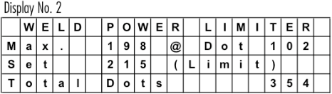

Corretive:

Readjust the weld power limiter, to a higher value. Observe the “Max” value from a “cold “ start to a “warm up” machine during production. See also note below.
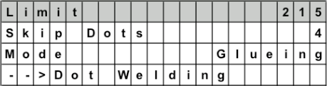
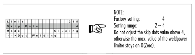

NOTE:

Power limit to activate the weld guard (stitch welding). Normally 5 – 10 % more than the actual “Max” value during production.
0 = Weld Power Limiter Off !


Possible cause:

  • Welding transformer has short circuit on primary side (see How to find out that the welding transformer is damaged / broken?)
  • The cable or isolation to the welding transformer is damaged
  • IGBT broken
  • Exchange the contacts (CM article 005640) of the main contactor, or the complete main contactor (CM article 003217).
    (NOTE: This is only applicable, if the error message shows up, when you start up the Pacemaker).
  • Cooling water valve: Wrong type of valve or plug without protective circuit (suppressor).The voltage peaks can cause interferences in the Pacemaker electronics. Always use the original plug and valve type.
  1. Switch off the main switch Q1 of the machine.
  2. Wait around 10min before you do anything on the wiring of the pacemaker! The capacitors need that time to discharge!!!
  3. Disconnect both welding cables from Pacemaker.
  4. Measure the resistant of both cable to earth. If the value is very low maybe the transformer primary side have short circuit to earth or the cables are damaged and make some contact to earth. If it looks ok (endless or very high resistant) go to point 5.
  5. Take the welding copper wire completely out of welder.
  6. Control that pendulum roller head is lift up. Put a carton or another insulating material between both welding rollers to make sure that you don’t have any contact between the rollers.
  7. Connect an external cable 230VAC (phase and neutral) to the welding cables, which you have removed on pacemaker before. Use for this external supply a 10A fuse breaker to protect the supply in case of a short circuit of welding transformer. (Take a look to picture on point 3)
  8. Before you switch on the external supply check again:
    – Wire removed?
    – Pendelum rollerhead lift up and isolation between welding rollers?
  9. Now switch on the external supply. If the 10A fuse breaker does not trip it is a good sign and it doesn’t look like short circuit of welding transformer.
  10. To control the output of welding transformer you can measure the voltage between the welding rolls (VAC). The measured voltage is depending on the type of welding transformer. If you change the transformer step this value has also to change. Check the output voltage of each step. Don’t worry if you measure only around 5VAC, the output voltage of welding transformer is a low voltage.

Before you change the transformer step switch off first the external supply!!!


Download PDF english

Download PDF chinese

If the voltage value drops below 350 V the error message “Phase voltage error” shows up.

Check the main supply: L1 / L2 / L3.


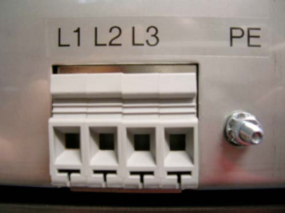
Check also the input directly inside the PM.
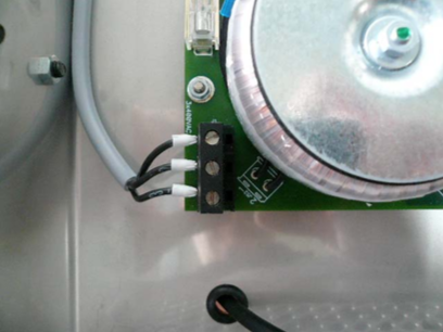
 

QM board defect?
A reason for a voltage error could also be a defect on the QM board, which receives it’s supply from the elec. board of the PM.
To verify a defect you can remove the supply cable. The voltage value should go up around 20V (e.g. 375V to 395V), which is normal. If the increase much bigger than 20V the QM board has a defect and need to be replaced.


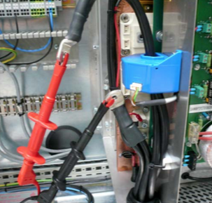
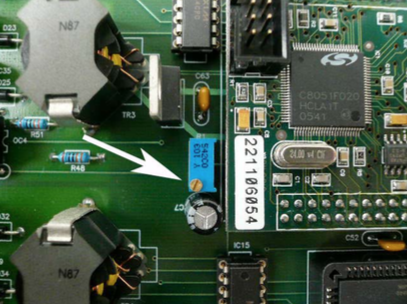
The voltage value on the touch screen is much lower than on the main terminal!

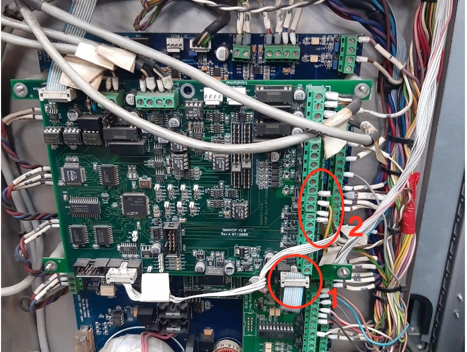
As a matter of fact, this electrical balancing of the two values has been done by CANMAN prior to the delivery. If there is a discrepancy you can adjust it.


You have to lose the small electronic board of Qualimaker (if applicable). This board is supplied by the big electronic board of PM. If you remove this supply cable, the voltage value goes up around 20V (e.g. 365V to 385V), which is normal.


Now measure the input of terminals, for example 385V. Turn the small blue potentiometer (picture). Control the value on touch screen. Must be around 20V more than the measured value, if you have a QM board. If you have adjusted it, connect the supply of QM and now you have the correct value on touch screen.
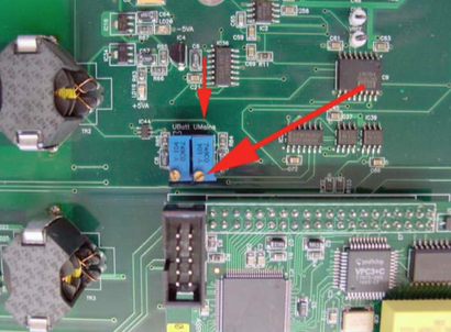
 

NOTE:
Starting with the version of the V4 mainboard, the board has two potentiometers. You need to adjust the “UMains” potentiometer in this case.

FAQ – Trouble Shooting

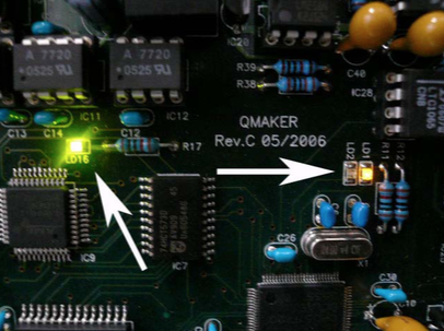
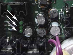
For the correct function of Qualimaker please check the 3 LED’s:
LD16 = state of profibus connection, must be on every time.
LD1 = program state, must be on every time.
LD2 = clock(cycle) of program, must be blinking.

Check the main supply
R-380VAC (L1), S-380VAC (L2), T-380VAC (L3).


Check if all green LED’s are “ON”.


Check in the display of pacemaker the actual displayed voltage R, S and T! (old version PM)


If you can see these values and one of them looks to low, you can adjust it with the three small potentiometer on left side of processor board (old version PM).

All Can Man content is now also available on the Soudronic Group website.
Where do you want to continue your journey?
All Can Man content is now also available on the Soudronic Group website.
Where do you want to continue your journey?