Support

13 Support Entries

Reason for error message:

  • The Pacemaker™  capacitor bank voltage is to low.


Possible causes:

  • Supply voltage mains drop down. Please check all phases even when the machine is running. Does a phase drop down?
  • Check complete wiring, Are all clamps tightened?
  • Check the 24Vdc supply terminals 17/18 on Pacemaker board. This 24Vdc are supplied by the welding machine and has to be always on. If the 24Vdc is missing, the precharging of capacitors works, but the main contactor will not switch on => Ubatt Error


  • Check the 24Vdc output terminals 41/42. After precharging is complete, 24DC should be applied here to close the main contactor. Possibly the small print relay on the electronics board is defective.


Problem:

Machine stops and message „Pacemaker: Profibus communication error“ is displayed.

Possible Causes & Resolutions:

  • Cooling water valve: Wrong type of valve or plug without protective circuit (suppressor). The voltage peaks can cause interferences in the Pacemaker electronics. Always use the original plug and valve type.
  • Profibus plug: On the plug of first and last client of profibus system the termination resistant must be set to ON. Otherwise interference may occur.
  • Profibus cables: Check the position of the cables in the control unit. If they are close to contactors, high voltage peaks can create interferences.
Problem:

Error message: Setup data corrupt / User data corrupt


Resolution:

Reason for error message:

  • The Pacemaker™ HF has detected a missing phase.


Possible causes:

  • Supply voltage mains (all three phases) 400V
  • Check the small fuses on the bottom of Pacemaker HF
  • Check complete wiring, Are all clamps tightened?
  • Measuring voltage at the input terminals on the main board (see attached picture)
  • IC “OC14” or phase measurement is defective. Replace the IC, Type HCPL3700

Possible cause:

  • Welding transformer has short circuit on primary side (see How to find out that the welding transformer is damaged / broken?)
  • The cable or isolation to the welding transformer is damaged
  • IGBT broken
  • Exchange the contacts (CM article 005640) of the main contactor, or the complete main contactor (CM article 003217).
    (NOTE: This is only applicable, if the error message shows up, when you start up the Pacemaker).
  • Cooling water valve: Wrong type of valve or plug without protective circuit (suppressor).The voltage peaks can cause interferences in the Pacemaker electronics. Always use the original plug and valve type.

Possible cause:

  • The power percentage is too high! If the power percentage rises up to 96%, the LED is flashing. In this case the pacemaker does not have enough spare power to regulate the current properly.

Corrective:

  • To solve the problem, reduce current/frequency value or use a higher transformer step.

Possible cause:

Problem:
The display shows the set current value, but the duty cycle is very low or 0%!

Possible cause:

  • Short circuit in the welding transformer!


DO NOT ATTEMPT TO SWITCH “ON” THE CURRENT ANYMORE!
Further attempts to switch on the current, can destroy or damage the semiconductors (IGBT) in the Pacemaker!

Possible Cause:

  1. Check air supply for the cylinder.
  2. Second light barrier is always ON.
    Sensor dirty or bad adjustment.
    LED on light barrier must be ON without can, OFF if a can is detected.
  3. Adjustment of the light barrier distance to eject cylinder might be wrong.

  4. Wrong adjustment of the transport belt speed.

Possible cause:

  • Check if the wire speed is stable and not too slow? Sometimes two cans might be welded together (no gap)!
  • Check if the speed of the exit conveyor is fast enough? The gap between the cans must be minimum of 10mm.
  • Clean the first light barrier and the reflector and check the adjustment!

If the voltage value drops below 350 V the error message “Phase voltage error” shows up.

Check the main supply: L1 / L2 / L3.


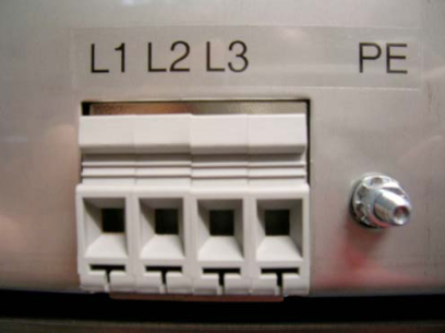
Check also the input directly inside the PM.


QM board defect?
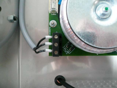
A reason for a voltage error could also be a defect on the QM board, which receives it’s supply from the elec. board of the PM.
To verify a defect you can remove the supply cable. The voltage value should go up around 20V (e.g. 375V to 395V), which is normal. If the increase much bigger than 20V the QM board has a defect and need to be replaced.


The voltage value on the touch screen is much lower than on the main terminal!

As a matter of fact, this electrical balancing of the two values has been done by CANMAN prior to the delivery. If there is a discrepancy you can adjust it.


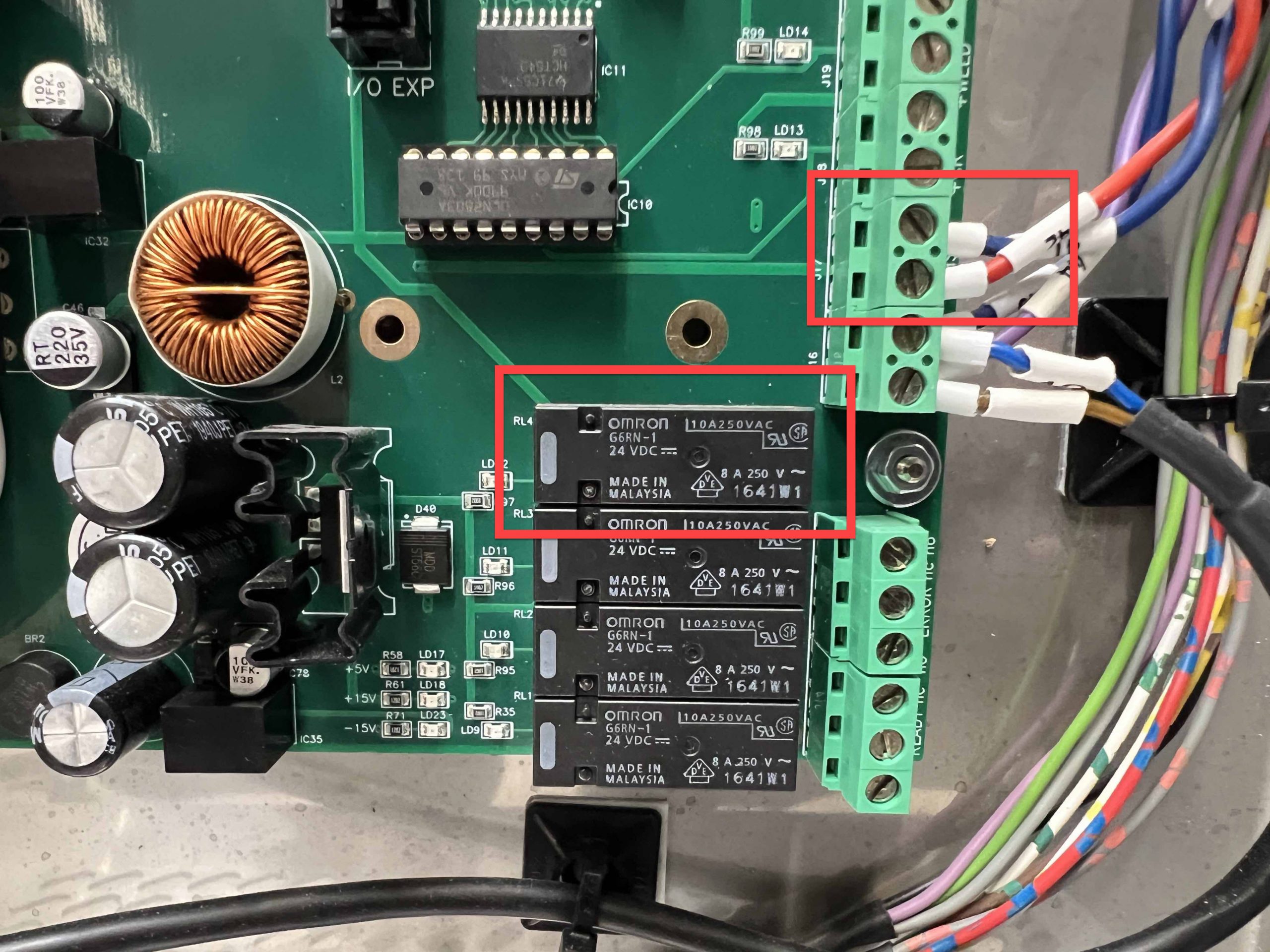
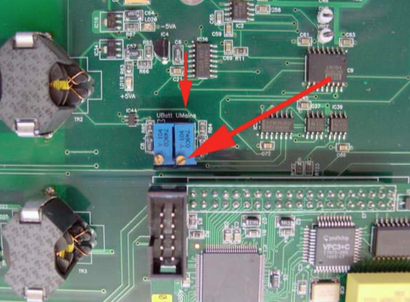
You have to lose the small electronic board of Qualimaker (if applicable). This board is supplied by the big electronic board of PM. If you remove this supply cable, the voltage value goes up around 20V (e.g. 365V to 385V), which is normal.


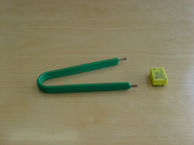
Now measure the input of terminals, for example 385V. Turn the small blue potentiometer (picture). Control the value on touch screen. Must be around 20V more than the measured value, if you have a QM board. If you have adjusted it, connect the supply of QM and now you have the correct value on touch screen.
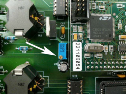
 

NOTE:
Starting with the version of the V4 mainboard, the board has two potentiometers. You need to adjust the “UMains” potentiometer in this case.

FAQ – Trouble Shooting

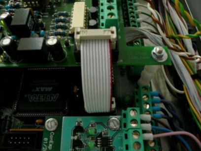
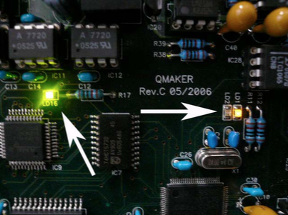
For the correct function of Qualimaker please check the 3 LED’s:
LD16 = state of profibus connection, must be on every time.
LD1 = program state, must be on every time.
LD2 = clock(cycle) of program, must be blinking.

Check the main supply
R-380VAC (L1), S-380VAC (L2), T-380VAC (L3).


Check if all green LED’s are “ON”.


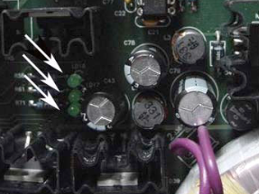
Check in the display of pacemaker the actual displayed voltage R, S and T! (old version PM)


If you can see these values and one of them looks to low, you can adjust it with the three small potentiometer on left side of processor board (old version PM).

  • Check can memory. Must be “0”, if there is no can between welding area and the reject station. For reset memory activate light barrier by hand or  use function “reset can memory”.
  • Check sensor on tool or light barrier.
  • Never take out can between welding area and eject station.
All Can Man content is now also available on the Soudronic Group website.
Where do you want to continue your journey?
All Can Man content is now also available on the Soudronic Group website.
Where do you want to continue your journey?