Support

5 Support Entries

Possible causes:

  • Check the blank cutting tolerances and blank squareness.
  • Adjust the rollformer (roller shaft clearance and spring pressure) according to the manual.
  • Control if there is a high difference in the tin plate hardness, by rollforming 10 bodies without welding. Put them on the floor in line and compare the difference in the rollforming overlap.
  • Check if the destacking process is going well. Make sure the tin plate is guided tight, and the separating air is positioned well.
  • Control the timing of the tin plate transport in between two transport fingers.
  • Make sure that the guidance channel is properly adjusted. The intersection to the precalibration of the calibration crown is most important.
  • Check the position of each (inside and outside!) transport finger compared to rollformed canbody.
  • Check the offset of each finger pair itself. Move the canbody slowly forward (X1 and X6 by slow mode function) and observe eventual shaking of the canbody until the welding point.
  • If a third finger exists: The third finger must be 0.5 mm behind the upper main pusher fingers!
  • Reset the calibration crown completely. Make sure that each precalibration roller is turning easily! If needed lubricate their shafts slightly and clean the roller afterwards. Make sure that these rollers are as close as possible to each other!
  • Measure the speed of the flat belt in the calibration crown:
    The speed must be absolutely identical with the copper wire speed!
  • Measure the overtravel: Short can heights shall have 1 mm overtravel.
  • The center of the diabolo roller (equal to the center of calibration crown) shall be 1–2 mm before the welding center.

This is the result of a wrong flexer setting!

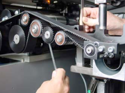
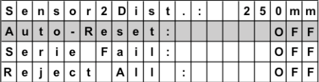
Open the rollformer and you undo the screw on the right handside of the “Flexer”.  

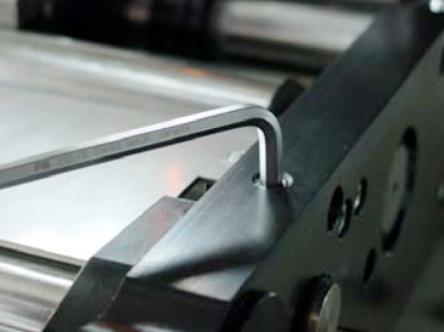
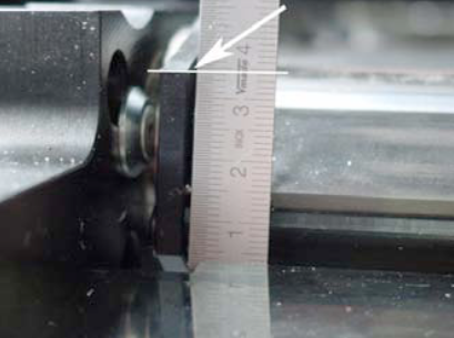
Measure with a ruler the actual position of the flexing wedge.

On the other side of the flexer, you can alter the position of flexer with the M8 screw. Choose a lower position for less flexing.

NOTE:
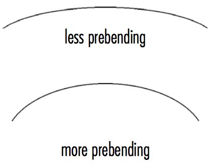
With more flexing the sheet comes out of the flexer station with less prebending.

If you do less flexing, means that the sheet comes out of the flexer station with more prebending.

NOTE:
After adjusting the flexer, you might have to adjust the rounding slighty!
For more information regarding the flexer and rollformer setting check our manual book 2 chapter 5.4.

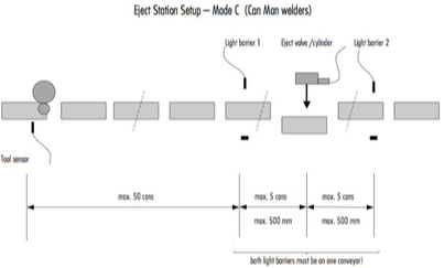
Possible Cause (CM16 / S, X8):

  1. Check air supply for the cylinder.
  2. Eject cylinder must push the canbodies inthe center, the can must move verticallyaway from eject cylinder.
  3. Second light barrier is always ON.Sensor dirty or bad adjustment.
    LED on light barrier must be ON without can, OFF if a can is detected.
  4. Control wiring of first and second light barrier according electrical diagram.
  5. Make sure the faulty can is really ejected, means does not touch the edge of the bin and jumps back.
    => Use a fixed channel underneath the eject station, instead of a mobile bin!

Adjustment of the light barrier distance to eject cylinder might be wrong.

Wrong adjustment of the transport belt speed.

NOTE:
The ejected can should whether touch the can before nor the following.

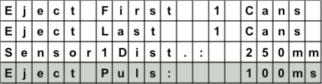
Eject pulse cylinder has to fit to production speed:

Recommendation: 150-200msfor<100cpm 100-150msfor100-200cpm

80-100msfor200-400cpm

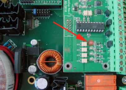
Place a canbody between the second light barrier and check the LED „LD3“ on the eject print (inside the Pacemaker).
Must be „ON“.

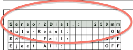
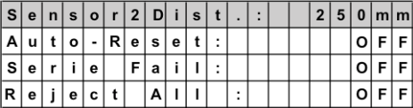
The autoreset needs to be “OFF”. Therefore the can memory will not be reset automatically.

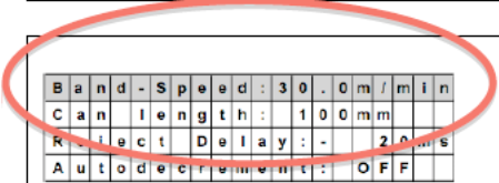
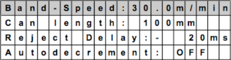
Check, if your hardware parameters are set correctly, according to one of the three layouts.
=> See layouts below!


Click here for more


Possible Cause (Pacemaker):

  1. Check air supply for the cylinder.
  2. Second light barrier is always ON.
    Sensor dirty or bad adjustment.
    LED on light barrier must be ON without can, OFF if a can is detected.
  3. Adjustment of the light barrier distance to eject cylinder might be wrong.

  4. Wrong adjustment of the transport belt speed.

Possible Cause:
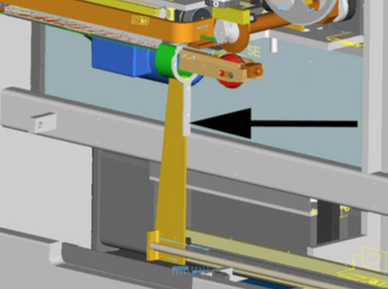
The position of the infeed arm might have shifted, due to a crash or loose screws!

double check the correct position.


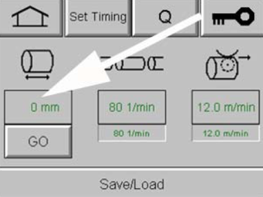
Therefore insert „0“ to the can height setting and press „GO“.

NOTE:
If you ever changed the overtravel setting in the tuning level, set this value to „1“.


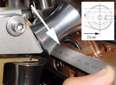
Now measure the distance from the infeed arm to center of the welding roll.


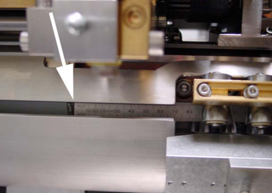
The correct reading should be: 216 mm!

NOTE:
With this reading the canbody will have 1 mm overtravel.


Find the correct position by undoing the four fixing screws of the infeed arm!
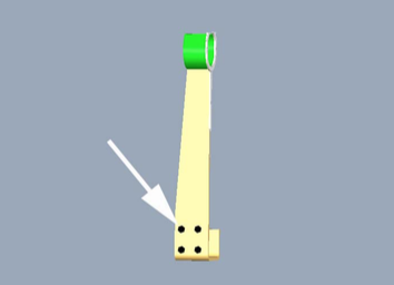
 

NOTE:
This adjustment described above, is only applicable for the old type of CMX8, since the new version has a slot to prevent this issue.
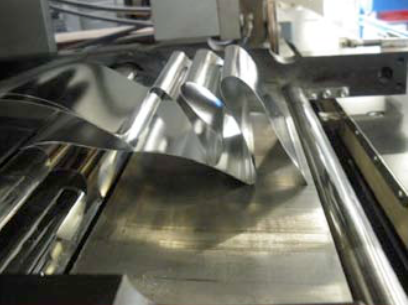
Possible cause:

This can only happen on higher can heights. The canbody to be welded, is extending with its back into the rollforming area, while the next tin plate is coming out of rollformer and touches the backside of the tin plate. The sharp edge of the rollforming plate scratches paint away. This paint is being welded thereafter in the seam.

 Correction:

  1. Reduce the Linmot cycle time, but not less than 500 ms (access with password customer 1). The can is now pushed faster into the welding area. This might already solve the problem.
  2. Adjust the timing of the feeder delay and compare to Linmot pusher (see manual book 1, chapter 4.5.3.)
  3. Increase rollformer speed if necessary, to reduce the rollforming process, because of delayed feeder.
  4. Try step 2 and 3 til ok.
All Can Man content is now also available on the Soudronic Group website.
Where do you want to continue your journey?
All Can Man content is now also available on the Soudronic Group website.
Where do you want to continue your journey?