Report all steps, new or different settings, and old and new production parameters (can size, cpm, weld speed, weld current, weld frequency, current wave-form and transformer step) for an easier overview and follow-up ! (www.canman.ch /Open new ticket and add your document)
Note on which tin-plate parameters (thickness, hardness, tin coating inside / outside, rolling direction, BA or CA, supplier, printed or not) such faults occur, and on which tin-plates not !
Basic parameters & settings to be checked first
- Tin-plates must be cutted within the allowed tolerances:
- Measure the tin-plates and report if out of tolerance!
- Follow sheet „blank-cutting tolerances“! (www.canman.ch/SUPPORT/Canmaking/002)
- Are all tin-plate parameter clear and noted: Thickness, hardness, tin coating in- and outside, rolling direction, BA or CA, supplier, printed or not
- Can-bodies must be correctly rollformed:
- Not conical and best roundness must be reached!
- Overlap of both tin-plates edges:
- ø 52 ~ 5 mm
- ø 99 ~ 15 mm
- ø 153 ~ 30 mm
- ø 284 ~ 60 mm
- The copper wire must be correctly profiled and the surface not damaged:
- The width of the profiled copper wire shall always be 0.05 mm smaller than the profile-groove in the weld rollers!
- Measure the width of the profiled copper wire within around half a meter on several position, and note the variations. Maximum difference of 0.05 mm is allowed. If you measure more, check the concentricity of the profiling rings.
- Change the copper wire profiling rings or idler/guide wheels if the surface of the copper wire shows a damage.
- Both weld rolls must be regrooved after its regular groove life-span:
- To avoid unexpected heavy weld faults, it is recommended to implement the total piece-counter and the regrooving interval into the production order!
- As an example:
- Upper weld disc ø 90 mm to be regrooved after 3 mio cans (interval depends on, type of welder, type of weld roll and welding speed).
- Lower weld roll ø 62 mm to be regrooved after 2 mio cans.
- Example: Total piece counter at production start at 28 mio welded can bodies, upper weld disc has been regrooved at 25 mio, therefore to be regrooved now! Lower weld roll regrooved at 27.5 mio, therefore to be regrooved at 29.5 mio.
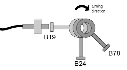
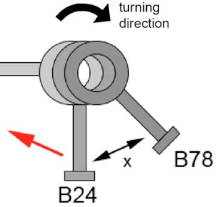
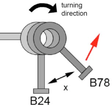
- After every regrooving, weld roll and / or z-bar must be repositioned: Use the correct tools to reset the lower weld roll and/or nose-piece, and the upper welding roller!
- The z-bar must be clean in and outside – and not worn -, calibration crown must be clean, and all pre-calibration rollers shall turn easily:
- A dirty z-bar may not be well insulated, therefore the risk of wear is higher and the weld current is flowing over z-bar and tin-plate to the weld center!
- Note: The insulation of the secondary circuit should be controlled yearly!
- Non-turning pre-calibration rollers can create body-offset and inconstant can gap!
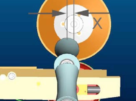
- The calibration crown center must be correctly positioned to the weld center:
- The center of the crown must stay between 3 – 0.5 mm before the center of the lower weld roll (in weld direction seen).
- The position and speed of the exit conveyor (all conveyors which transport the can body out of the weld center) must be aligned perfectly.
- Both belts of any V-Shape conveyor need to have a gap of 0.3 – 0.5 mm to the can body. If available use a setting mandrel instead of a can body. The alignment of the conveyor must be absolutely parallel to the weld direction!
- The gap between two can bodies on the exit conveyor should not be higher than10 – 20 mm! (if can gap is 1.0 – 3.0; see „can gap“ in point 12.)
- A driven diabolo roller / bottom conveyor after the diabolo rollers must run the same speed like the copper wire!
- Both tin-layers must be centered and parallel to the copper wire:
- That means that all mechanical settings are correct!
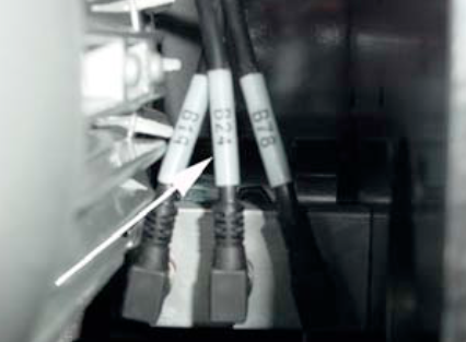
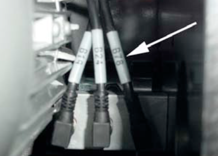
- The copper wire tension and elongation must be correct:
- Make sure that the air-pressures for the pneumatical cylinders are set correctly, or the copper wire is in the right groove of the wire drive disc (Soudronic m/c’s only).
- Measure the copper wire elongation after the lower weld roll, or after the weld roll before the wire chopper: Elongation varies under normal conditions between 0 – 4 % of the can body height.
- A sufficient copper wire tension is important to avoid a slipping copper wire on the weld rolls!
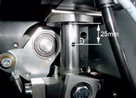
- The can body overtravel must fit:
- Set the overtravel according manual / scale on the transport carriage!
- Measure how many mm the can body will be pushed over the center of the weld rolls.
- The welding pressure must be set correctly:
- Welding pressure for Wima welders vary between 35 and 50 kg / daN. Start with ~ 45 kg / daN (if needed check the manual to convert in bar).
- 50 Hz Wima welders using welding pressure between 35 – 50 kg/daN as well.
- The welded overlap must be correct, and on beginning and end within allowed tolerances:
- Correct welded overlap depending on z-bar:
- Z-bar of 0.3 mm results in a welded overlap of 0.4 – 0.5 mm
- Z-bar of 0.4 mm results in a welded overlap of 0.5 – 0.6 mm
- Z-bar of 0.6 mm results in a welded overlap of 0.6 – 0.7 mm
- Z-bar of 0.8 mm results in a welded overlap of 0.8 – 0.9 mm
- If the overlap is not correct, adjust until overlap is correct:
- Reset the calibration crown if needed with the mandrel. The diabolo-rollers should not have any radial-play!
- Adjust the overlap according manual.
- Once the overlap has been set, double check and set the can gap. Increasing the overlap will reduce the can gap, decreasing the overlap will increase the can gap.
- Weld around 5 cans and measure the gap between the tin-layers. A good can gap measures between 1.0 – 3.0 mm (depending on the can body format). Any variation should be within 0 – 1.0 mm.
- The weld current frequency must fit:
- Welders with a static frequency inverter should have a welding spot length between 0.6 – 1.2 mm.
- A welder without static frequency inverter should be operated between 8 – 12 m/min. Reducing the welding speed does decrease the welding spot length.
- The welding spot length should always be as long as possible (by reducing the frequency) to reduce energy and heat in the welding seam and in the welder to a minimum.
- Main target must be a flexible and smooth welding seam!
- The main weld current must be set correctly!
- How to do:
- Reduce weld current until cold weld zones appear. Tear-off test must be done at an angle of 30 – 45°, means try to pull-off the top tin plate edge. To be done from each side. Note the weld current value!
- Increase weld current until hot weld appears. Tear-off test must be done at an angle of 0°, means pull-off the seam only and find out when the seam starts to become fragile. Note the weld current value!
- Add 2/3 of the weld current difference between cold and hot weld seam to the cold weld seam value, and start the production!
- Set beginning and end time and beginning and end current!
- Note: If the welder is running with triangle wave-form, make sure the duty-cycle is between 80 – 90 %. If the welder is running with sine wave-form, make sure the right transformer step has been choosen! Contact us if you are not sure.
- The seam-extrusion inside and outside must be equal!
- If the seam extrusion is bigger inside, reduce the height of the calibration crown. If the seam extrusion is bigger outside, increase the height of the calibration crown.
Checklist to Avoid Micro Leaks
Micro leaks can occur within the seam and beside the seam – especially on cold-formed areas like necking, beading, flanging or seaming -, even if all above mentioned basic parameters & settings seems to be correct.
Micro leaks can have various sources: Wrong settings on the welder, tin-plate parameters which support such faults, worn or wrong machineries in the downline, or tin-plate parameters which do not fit to beader, necker, flanger and seamer.
For a better visual understanding put the faulty-can bodies in a water bath, and inspect the leaking area by a microscope. Store the pictures if possible!
- Make sure that necker, flanger, beader and seamer are in good condition, and do not stress the weld seam more than needed.
- For further information check the manuals (check the tin-plate specifications range) or contact the supplier!
- Try to weld different tin-plates to understand which tin-plate parameter can be produced without such faults.
- Rolling-direction parallel to weld seam can increase the occurrence of micro-leaks!
- Micro-leaks in and near the seam can be reduced by changing the energy in each welding spot:
- Reduce the welding frequency within the possible range (see point 13. in above checklist), and set the main weld current again (see point 14. in above checklist). The production cycle (cpm) must probably be reduced to reach a good weld seam. Produce a certain number of cans and test them.
- Increase the welding frequency within the possible range, and set the current again. Produce a certain number of cans and test them.
- Reduce the welding pressure to max 45 kg / daN, and set the main weld current again (see point 14. in above checklist). Produce a certain number of cans and test them.
- Reduce the welded overlap by around 0.10 mm, and set the main weld current (see point 14. in above checklist). Produce a certain number of cans and test them.
Checklist to Avoid Flange-Cracks
Flange cracks can occur at the beginning and the end of the seam, even if all above mentioned basic parameters & settings seems to be correct.
Flange cracks can have various sources: Wrong settings on the welder, tin-plate parameters – for instant parallel rolling direction – which support such faults, worn or wrong flanger in the downline, or tin-plate parameters which do not fit to the flanger and or seamer.
For a better visual understanding put the faulty-can bodies in a water bath, and inspect the leaking area by a microscope. Store the pictures if possible!
- Make sure that flanger and seamer are in good condition, and do not stress the weld seam more than needed:
- For further information check the manuals (check the tin-plate specifications range) or contact the supplier!
- Try to weld different tin-plates to understand which tin-plate parameter can be produced without such faults:
- Rolling-direction parallel to weld seam will increase flange cracks, because the seam cracks in line with the rolling direction!
- Weld tin-plates with cross rolling direction and test them.
- Flange cracks can be reduced by changing the energy in each welding spot:
- Reduce the welding frequency within the possible range (see point 13. in above checklist), and set the main weld current again (see point 14. in above checklist). The production cycle (cpm) must probably be reduced to reach a good weld seam. Produce a certain number of cans and test them.
- Increase the welding frequency within the possible range, and set the current again. Produce a certain number of cans and test them.
- Reduce the welding pressure to max 45 kg / daN, and set the main weld current again (see point 14. in above checklist). Produce a certain number of cans and test them.
- Reduce the welded overlap by around 0.10 mm, and set the main weld current (see point 14. in above checklist). Produce a certain number of cans and test them.
- Activate the current reduction on the begin and end to reduce the heat in the first few welding spots.
- If above listed does not help, some theoretically wrong settings could help:
- Increase the can gap to have completely different welded begin and end. Produce a certain number of cans and test them, and set back if it didn’t help!
- Set a slight can-body offset, to bring the current different into the tin-plate. Produce a certain number of cans and test them, and set back if it didn’t help!