How to bypass / remove a generator in case of failure on the PowerCURE V2 please check link below:
Problem:
Circuit breaker Q5 trips when the machine is switched on or during production.
Possible Causes or Resolutions:
Reason for error message:
Possible causes:
Problem:
Machine stops and message „Pacemaker: Profibus communication error“ is displayed.
Possible Causes & Resolutions:
Error message: Setup data corrupt / User data corrupt
Resolution:
How To:
Reason for error message:
Possible causes:

For a Pacemaker-repair we calculate / estimate a “cycle-time” of 2 weeks, including final testing and packing. If a faster service is required, extra charges occur. In case the number of incoming repair jobs is unusual high, it might take more than 2 weeks.
Possible cause:
Corrective measure:
Possible cause:
Corrective:
Cause:
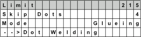
The actual value of the weld power limiter increases with the heating of the machine.
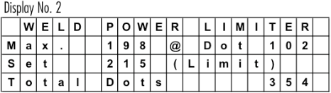
Corretive:
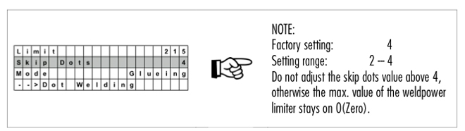
Readjust the weld power limiter, to a higher value. Observe the “Max” value from a “cold “ start to a “warm up” machine during production. See also note below.
NOTE:
Power limit to activate the weld guard (stitch welding). Normally 5 – 10 % more than the actual “Max” value during production.
0 = Weld Power Limiter Off !
Download PDF here
Problem:
The display shows the set current value, but the duty cycle is very low or 0%!
Possible cause:
DO NOT ATTEMPT TO SWITCH “ON” THE CURRENT ANYMORE!
Further attempts to switch on the current, can destroy or damage the semiconductors (IGBT) in the Pacemaker!
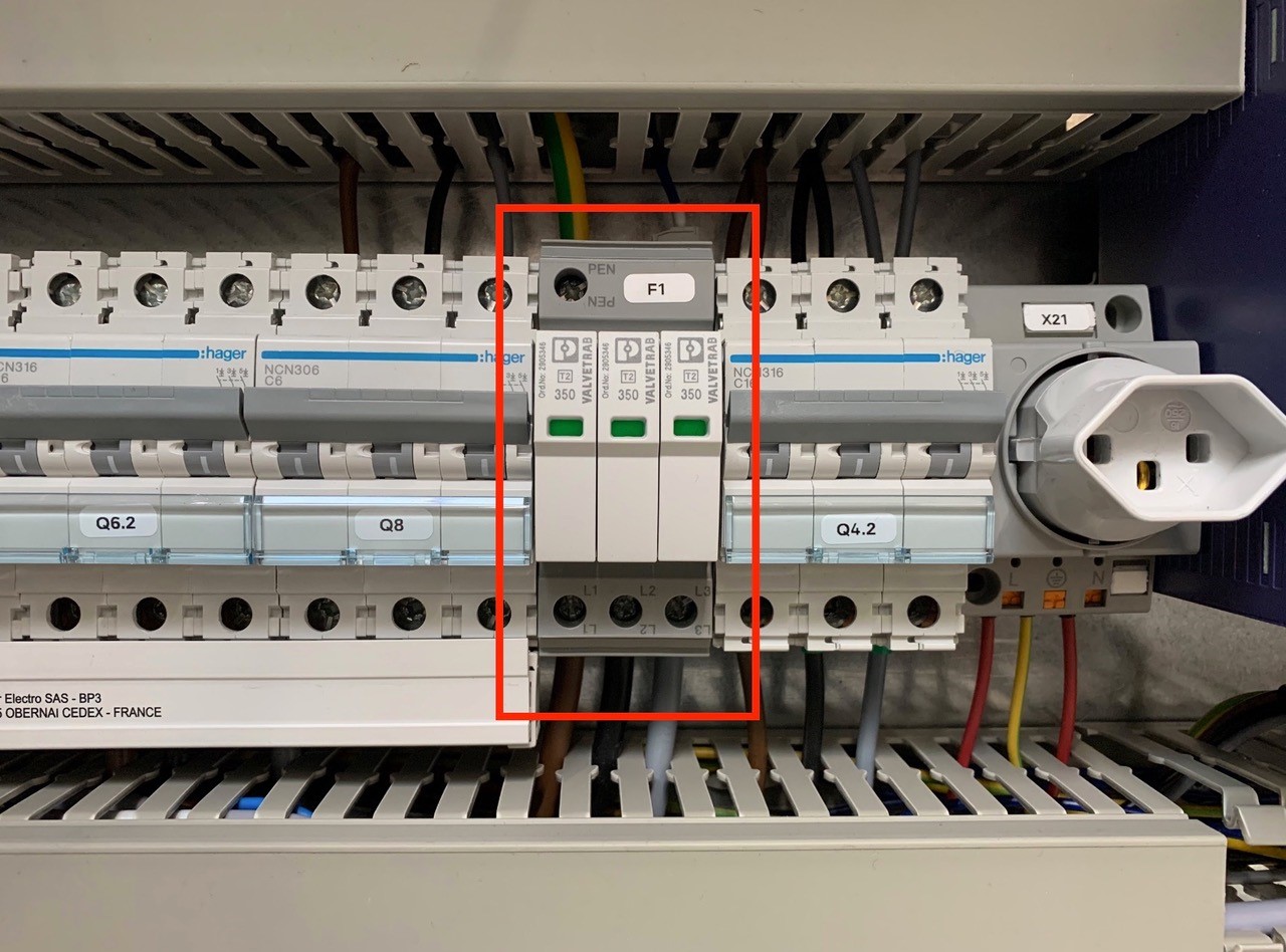
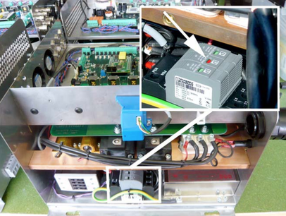
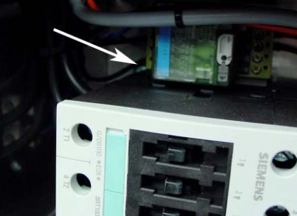
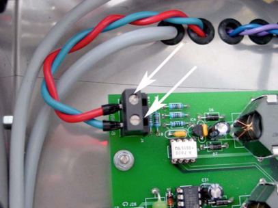
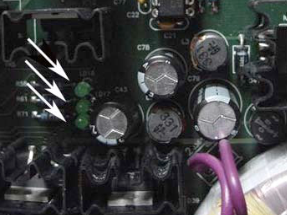
An overvoltage suppressor (or surge suppressor) is an appliance designed to protect electrical devices from voltage spikes. A surge suppressor attempts to regulate the voltage supplied to an electric device by either blocking or by shorting to ground voltages above a safe threshold.
These surge suppressors are built in to the latest Pacemaker models and machine controls (from 2009).
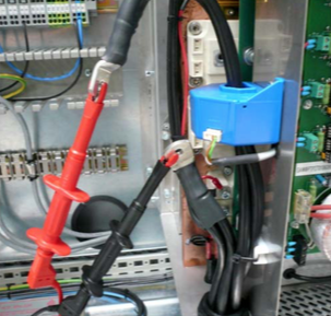
Check, if one or more modules of the surge suppressors are red/defect. Replace the red modules.
Attention!!!
Do not bridge the signalling contacts and run the machine with defective red modules because they no longer protect the system from voltage peaks!!!
If the modules are defective, check the main supply. Measure and check all voltages between the phases and all phases to earth before exchange the modules and restart the machine.
Important requirements:
Possible problems, if the overlap function does not work!
Possible cause:
The Pacemaker™ static welding inverter has a RAM battery for data retention and clock-buffering at power interruption/disconnection. The battery has a limited life span (about 5 years) that decreases especially without power supply (controller off). To prevent loss of data, the battery must be replaced early enough > ONLY BY AUTHORIZED AND SKILLED PERSONNEL!
To order a new battery please contact spares.canman@soudronic.com.
For instructions on how to replace the battery use the download link below. You will also find the correct order number there.
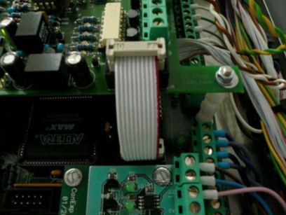
How to change the battery on a Pacemaker™ with integrated Qualimaker V1 electronic board:
Possible Cause:
Possible cause:
Using a handpanel:
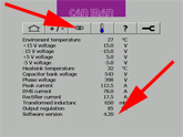
When you start up your Pacemaker, the software version will be displayed during the boot process.
Alternatively the information will we displayed, when you press the key “down” several times until you get to “Info Version”: e.g. 5.27
Using a CM16 welder you will also find the info by pressing the key “down”, since the display is the same as the handpanel of a PM.
Using a X1 welder:
Tip on the *eye” icon and the Pacemaker software version is displayed on the bottom line.
Using X8 welder:
Tip on the “eye” icon and then on a second “eye” icon to get to software version info on the bottom line – check also your manual book 1 – chapter 4.6. how to find the info.
Possible cause:
Before you change the transformer step switch off first the external supply!!!
Download PDF english
Download PDF chinese
Problem:
Possible cause(s):
NOTE: The reason for the low current is due to an open circuit. The wire might be also hot in this case. If you have in general a high power percentage you might reduce the frequency.
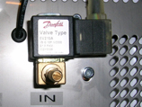
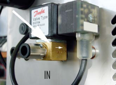
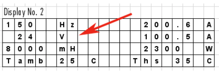
Scroll down in the display menu until you reach the temperature display. Observe, if after crossing the switching threshold, the temperature doesn’t change, that the solenoid valve is blocked (when the 2nd thresholds are reached the message “over- or undertemperature” will be displayed).
NOTE: The error message “Ths too low (Ths = Temperature Heatsink)” might be an indication for a contaminated valve.
Possible cause:
The Pacemaker has the following options to connect the output of the weld power limiter to other systems/controls (i.e. can rejection control):
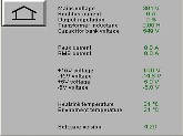
If the voltage value drops below 350 V the error message “Phase voltage error” shows up.
Check the main supply: L1 / L2 / L3.
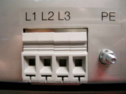
Check also the input directly inside the PM.
QM board defect?
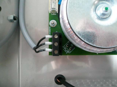
A reason for a voltage error could also be a defect on the QM board, which receives it’s supply from the elec. board of the PM.
To verify a defect you can remove the supply cable. The voltage value should go up around 20V (e.g. 375V to 395V), which is normal. If the increase much bigger than 20V the QM board has a defect and need to be replaced.
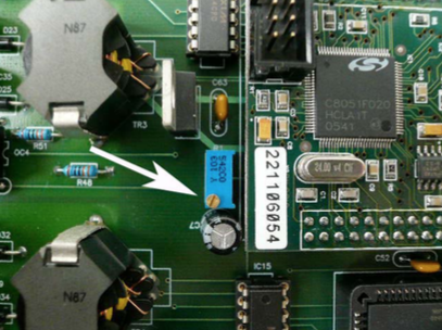
The voltage value on the touch screen is much lower than on the main terminal!
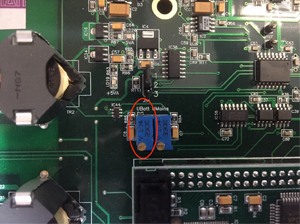
As a matter of fact, this electrical balancing of the two values has been done by CANMAN prior to the delivery. If there is a discrepancy you can adjust it.
You have to lose the small electronic board of Qualimaker (if applicable). This board is supplied by the big electronic board of PM. If you remove this supply cable, the voltage value goes up around 20V (e.g. 365V to 385V), which is normal.
Now measure the input of terminals, for example 385V. Turn the small blue potentiometer (picture). Control the value on touch screen. Must be around 20V more than the measured value, if you have a QM board. If you have adjusted it, connect the supply of QM and now you have the correct value on touch screen.
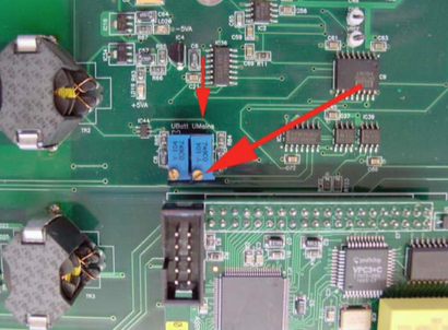
NOTE:
Starting with the version of the V4 mainboard, the board has two potentiometers. You need to adjust the “UMains” potentiometer in this case.
FAQ – Trouble Shooting
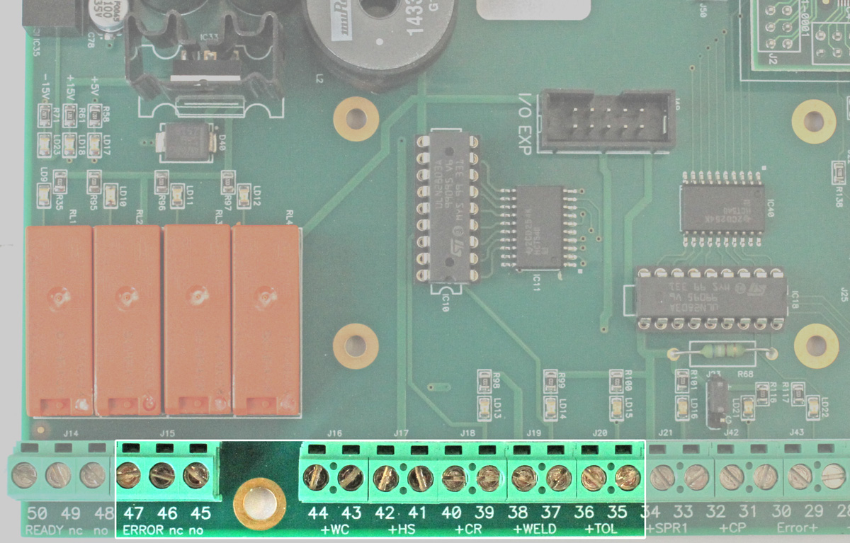
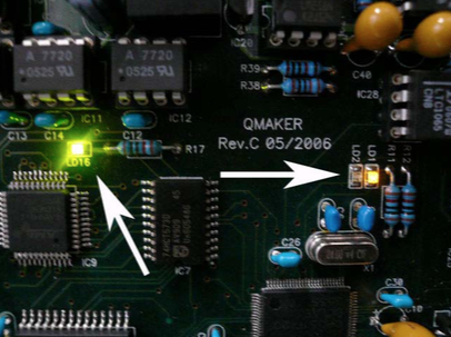
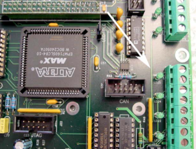
For the correct function of Qualimaker please check the 3 LED’s:
LD16 = state of profibus connection, must be on every time.
LD1 = program state, must be on every time.
LD2 = clock(cycle) of program, must be blinking.
Check
– Check the cooling-water-inlet.
– Check the “Ths” and “Tamb” on the display.
– Check the small fans of the Pacemaker
NOTE:
The error “Ths too low” means temperature heat sink (copperplate) too low. If the copper plate is too cold. It can damage the unit, if some condensation water flows to the electronic power parts.
Check if the valve closes correctly and clean the valve.
NOTE:
If you reassemble the valve, make sure you do it the right way (see picture)
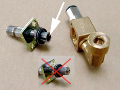
Check the correct water flow direction.
Download PDF here
NOTE: The pictures showing a regular Pacemaker and not a Pacemaker HF as used in the PowerCure, but the issue is the same!
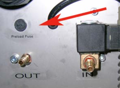
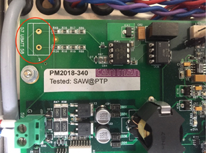
Check the fuse on the bottom side, near the mains electrical (only PM 400/500 – PM Micro has no fuse!)
Check also the cable on this holder, it might have bad or oxidised contact!
USE 2A T (slow) FUSE
DO NOT USE LARGER OR FAST TYPE OF FUSE!
Check, if one or more modules of the surge suppressors are red/defect. Replace the red modules.
NOTE:
These surge suppressors are only built in to the latest PM models (from 2009).
ATTENTION:
Do not bridge the signalling contacts and run the machine with defective red modules because they no longer protect the system from voltage peaks!!!
If the modules are defective, check the main supply. Measure and check all voltages between the phases and all phases to earth before exchange the modules and restart the machine.
Make sure that you do all the actions with the necessary care and that all manipulations and measures are done by a certified electrician and with a well insulated multimeter! However do not manipulate inside the unit before the front panel display shows a low U batt (<24V)-(condensator battery voltage)!

With main switch on, switch on the inverter and monitor the charging of the battery voltage (Ubatt).
If the charging process starts normally and the battery voltage (Ubatt) constantly increases above 360V, then stops and pre charge error appears, it may be that the limit for activating the main contactor is not reached. The reason can be a slightly lower 3-phase main supply. If you have measured all phases and they are stable only slightly lower, open a Canman support ticket to get information on how to adjust the limit for activating the main contactor.
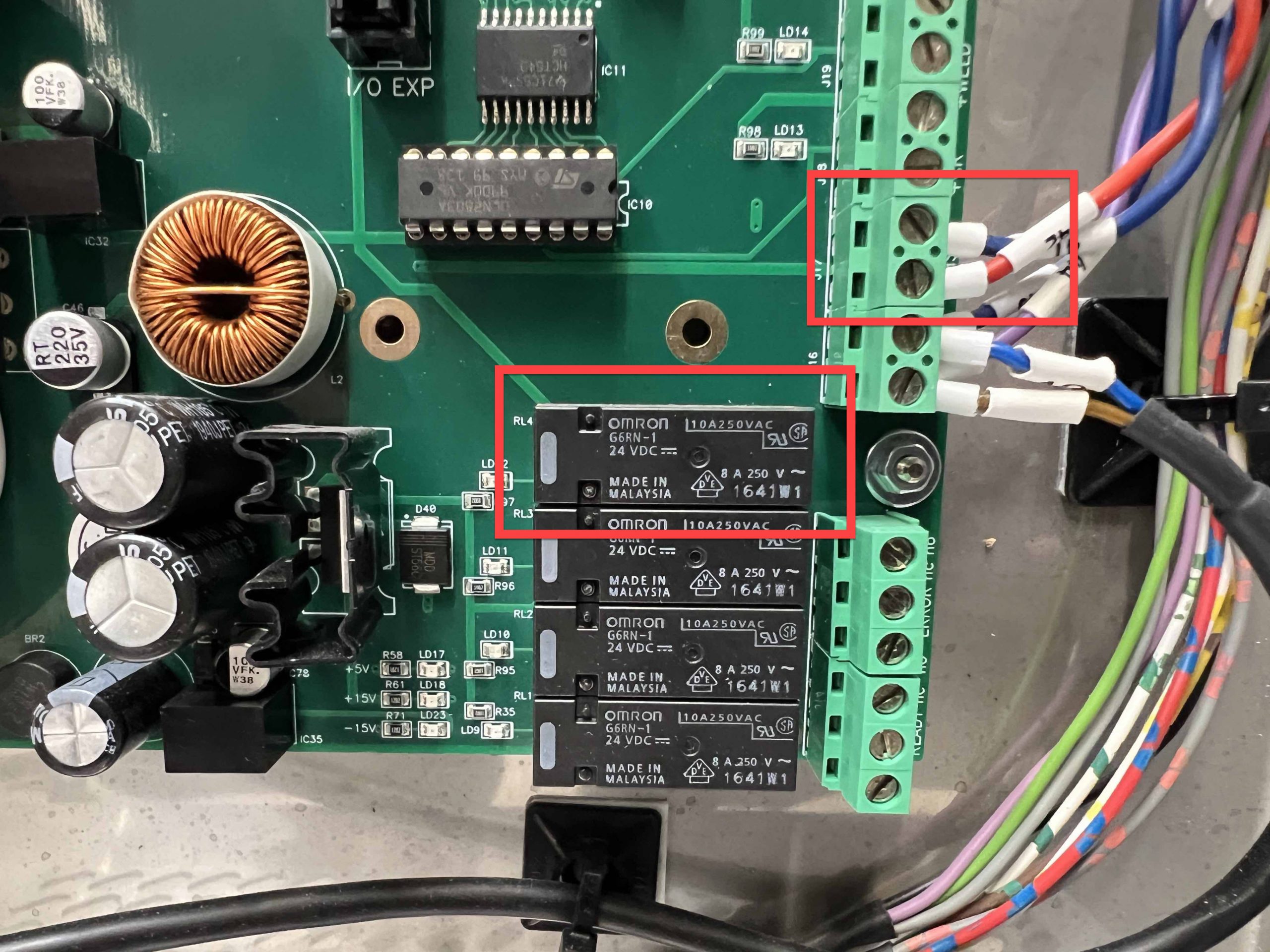
If battery voltage does not at all increase, you may check the function of the “small precharge relay” and its output on the main board.
There is an LED (LD25) on that output showing the state of this output. If the precharge relay doesn’t react you may check the wiring.
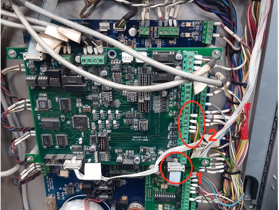
If the battery voltage increases, but the “precharge time out” appears while the voltage is still increasing, it could be that.
a) a phase is missing or has an “under voltage”, therefore you should check the voltage of all three phases (also to ground!)
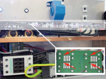
b) it could be that the rectifier (1) or even worse a condensator or an IGBT (2) is malfunctioning.
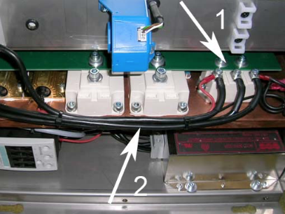
Measure the actual battery voltage and compare it to the display (Ubatt). (ATTENTION: Switch off the unit and wait ’til the battery voltage is low, before you remove the front cover!). The voltage could be beyond 550 Volt DC, so please use a voltmeter, which has the necessary range. The terminals are on the left top (usually red and blue coloured).
If the voltage shown on the display does not correspond to the measured voltage, it can be adjusted with the potentiometer.
During loading, check the LED on the power board, which connects to the condensers. Are they glowing up at the same time? After loading are LED’s still on?
If not one more condensers might bad or defect!
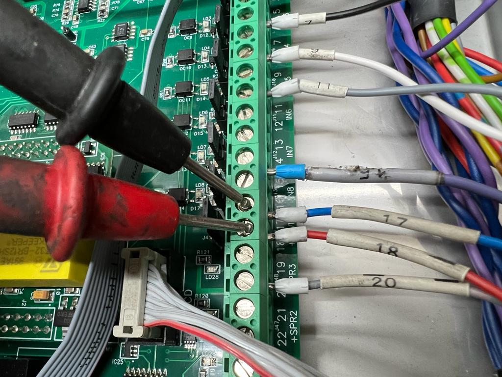
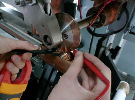
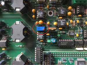
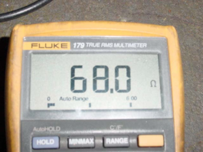
To check the preload resistors, you can measure the resistance with the Ohmmeter, between the relay contact “14” and the recitfier (red wire) and contact “24” and the recitfier (black wire) – see picture beside.
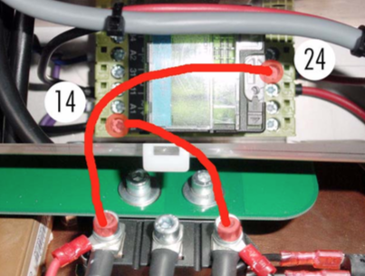
The result should be 68.0 Ohm.
Possible cause, the signal “reduce current” is always active. With reduction switch on there is no measuring, that means “Ctol” and “Power Limiter”are not active.
Check the signal “reduce current”. Maybe the electronic card of the machine is defective.
Questions:
Do you have instructions on how to upgrade our current Pacemaker software? Yes.
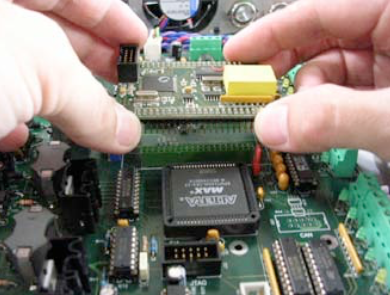
Change of the processor board
The software for the Pacemaker is memorized on a small processor board. For an update with new software you need to change this board.
IMPORTANT:
Before you start to change the board write down all values/parameters (e.g. main current, frequency etc.) for each can you have saved in pacemaker memory.
This not necessary for the CMX1 and X8 welder, because the parameters are safed in the panel.
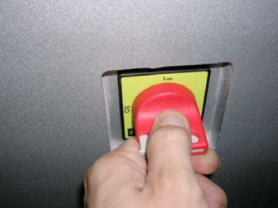
Switch of main switch of pacemaker / machine.
WARNING:
Wait 5 minutes before you remove the cover. Capacitors with high voltage inside!
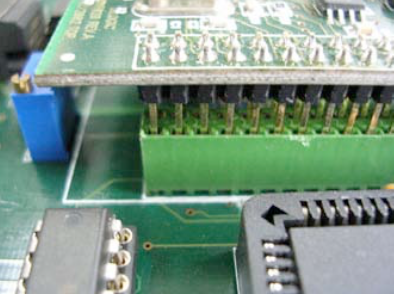
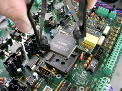
Remove the processor board carefully by hand. Do not use any tools for that.
Install the new processor board.
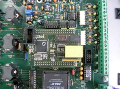
Be careful about the board position and especially the position of the connectors.
NOTE:
Depending on your current Pacemaker version you have to change the MAX IC as well.
The MAX IC controls all outputs and IGBT`s and works also with a software.
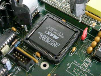
NOTE:
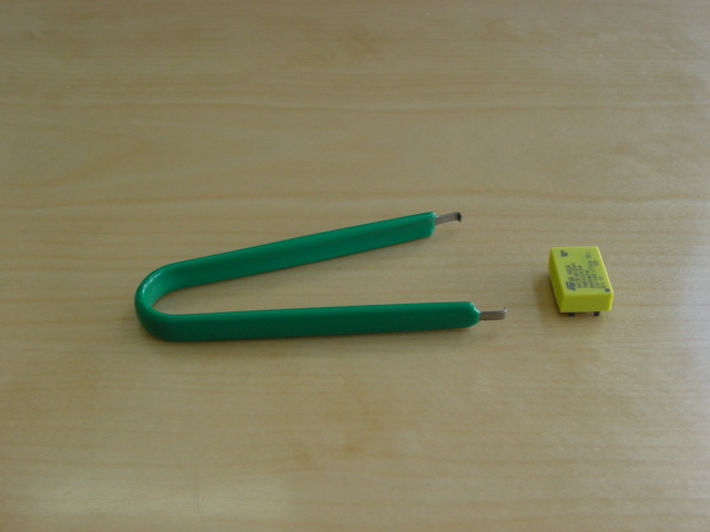
To remove the IC, use the delivered special tool. Never use a screwdriver or another tool. You will destroy the socket!
Take MAX IC out with the designated tool.
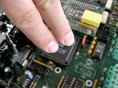
Install the new MAX IC.
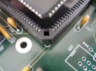
Double-check the position before you press the IC in the socket!
Switch the main switch “ON” and check all parameter (current, frequency, etc.) before you start production.
Check the main supply
R-380VAC (L1), S-380VAC (L2), T-380VAC (L3).
Check if all green LED’s are “ON”.
Check in the display of pacemaker the actual displayed voltage R, S and T! (old version PM)
If you can see these values and one of them looks to low, you can adjust it with the three small potentiometer on left side of processor board (old version PM).

If you have connect the control panel and you can see only strange signs in the display, the connecting speed can be wrong. The Pacemaker control panel can run in two modes.
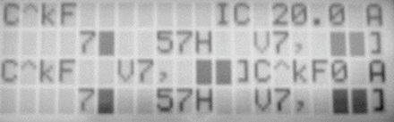
19200 baud
Control panel standard is 19200 baud (Used for connecting between control panel and PLC )
9600 baud
9600 baud (Used only for connecting between PLC and Pacemaker)
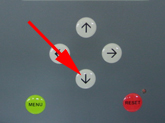
How you can change to 9600 baud:
Switch off the Pacemaker (Main switch off)
Press the “MENU” button while starting the panel. ![]()
Now the control panel runs with 9600 Baud Can Man machines with PLC.
How you can change to 19200 baud:
Switch off the Pacemaker (Main switch off)
Press the “RESET” button while starting the panel. ![]()
Now the control panel runs with 19200 baud
Control panel and PLC.
19200 baud
Control panel standard is 19200 baud (Used for connecting between control panel and PLC )
9600 baud
9600 baud (Used only for connecting between PLC and Pacemaker)
How you can change to 9600 baud:
Switch off the Pacemaker (Main switch off)
Press the “MENU” button while starting the panel. ![]()
Now the control panel runs with 9600 Baud Can Man machines with PLC.
How you can change to 19200 baud:
Switch off the Pacemaker (Main switch off)
Press the “RESET” button while starting the panel. ![]()
Now the control panel runs with 19200 baud
Control panel and PLC.
Possible Cause (CM16 / S, X8):
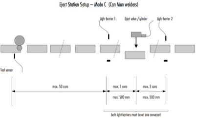
Adjustment of the light barrier distance to eject cylinder might be wrong.
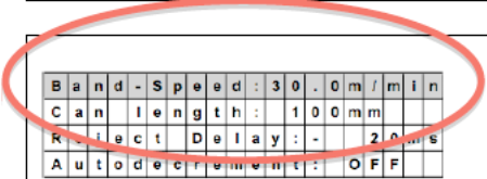
Wrong adjustment of the transport belt speed.
NOTE:
The ejected can should whether touch the can before nor the following.
Eject pulse cylinder has to fit to production speed:
Recommendation: 150-200msfor<100cpm 100-150msfor100-200cpm
80-100msfor200-400cpm
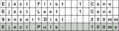
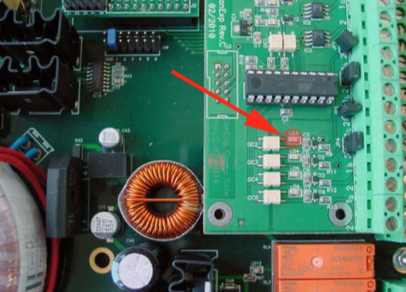
Place a canbody between the second light barrier and check the LED „LD3“ on the eject print (inside the Pacemaker).
Must be „ON“.
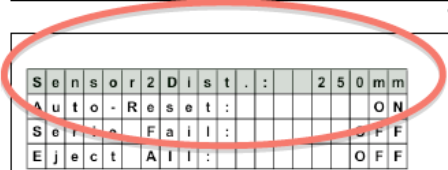
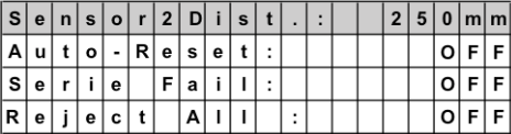
The autoreset needs to be “OFF”. Therefore the can memory will not be reset automatically.
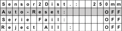
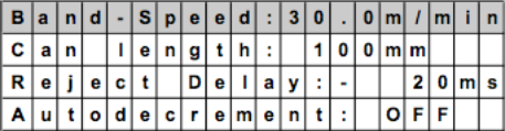
Check, if your hardware parameters are set correctly, according to one of the three layouts.
=> See layouts below!
Possible Cause (Pacemaker):