Support

44 Support Entries

Please consider the following suppliers for various raw materials:

Raw Material Suppliers

Copper Wire Suppliers

Question

How are the blank cutting tolerances?

Resolution

Please check the PDF Blank Calculations and Tolerances

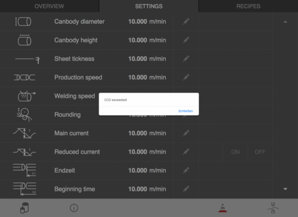
What does this error message mean?
CCD = concurrent connected data variables.

The amount of active CCD is limited. Opening the HMI is using some of the available CCD.
Closing the HMI is releasing the CCD again.
When you repeatedly open and close the browser, the CCD can still be in use and getting into the limitation.
(There is a delay for releasing the CCD when closing the connection).
„If a client wants to subscribe to new data variables while no more CCDs are available, a message “CCD exceeded!” will appear and there will be no communication with these data variables.“
„If a client disconnects from the visu (e.g. browser gets closed), it will take some time until the browser session expires and the CCDs from this client become available once again (session timeout of the scada server: 2 min.).

How to solve a CCD exceeded?

Close alle open browser connection (HMI app) and wait for >2 min.
Now you should be able to open the HMI without error message.

Closing apps on iPads with a home button:

  1. Double-click the Home button to show your most recently used apps.
  2. Swipe right or left to find the app that you want to close.
  3. Swipe up on the app’s preview to close the app.

Closing apps on newer iPads without a home button:

  1. From the Home Screen, swipe up from the bottom of the screen and pause in the middle of the screen.
  2. Swipe right or left to find the app that you want to close.
  3. Swipe up on the app’s preview to close the app.


How to prevent a CCD exceeded?
Don’t open the HMI in several browser simultaneously.
Don’t repeatedly open and close the HMI in short time.
Don’t repeatedly press reload the HMI in short time.


Possible cause/checklist:

  1. Slitter:
    • Angular errors below 0.05 mm per 100 mm
    • Burrs below 20% of tin plate thickness !
  2. Air pressure:
    • Welding pressure 2.6 (aerosol) to max. 2.8 bar (beverage, food), equal to 45 – 48 daN.
    • Wire tension cylinder profiling unit 1.6 bar
    • Wire chopper 2.4 bar
    • To move tooling (which air regulator find on touch screen: “Air”, page 5/8) pressure should be 3.0 bar.
    • To lift up guidance channel (page 5/8) pressure should be 1.0 bar.
  3. Lower welding arm/Z-bar:
    • Take off the upper and lower screw off one by one, check the insulation washers, if they are squeezed too much, change each them!
    • Check the insulation of the complete Z-bar:  > 10 MegaOhm
    • Measure the deflection of the X-Plane at a welding pressure of 45 daN (2.6 bar): Between 0.1 – 0.15 mm
  4. Check all the Z-bar grooves:
    • Especially the last 100 mm, incl. front Z-bar tip (called nosepiece), maybe they are worn out.
    • Sometimes some tin deposits can slow down or disturb the movement of the tin plates -> can gap unsconstant, cold begin/end.
  5. Welding roller grooves:
    • They have to be clean and the ground of each groove must be straight!
    • If you are not sure, re-groove them
  6. Copper wire width:
    • Check this according manual. Guideline: Width of copper wire always between 0.03 – 0.07 mm below profile width of welding rollers
  7. Reset the whole tooling according manual (if not yet available in your manual, ask Can Man)
    • Reset the calibration crown /tooling: Check the play of the top diabolo roller bearings.
  8. Lower welding roller height:
    • Set it around 0.3 mm over the Z-bar center. How to do:
      • Weld cans, and check the roundness:
      • Apple shape: Tooling too high, or welding roller too low or check this FAQ here
      • Roof shape: Tooling too low, or welding roller too high
      • The height of the tooling should be between – 0.2 and + 0.2 mm, shown on the handle/shaft underneath the tooling. If needed, move the height of welding roller again, till the roundness of the can is sufficient.
  9. Reset the upper pendulum rollerhead:
    • Angle: Normally not necessary, as long as nobody touched/dis-adjusted red marked screws on the support).
    • Horizontal axle: Make sure that the height of the pendulum axle is parallel to the welding roller axle. Use for this setting a precise level, and level the shaft of the pendulum rollerhead according the level of the welder, or do it according the manual, using the delivered gauge set.
  10. Position of exit conveyor:
    • Use the delivered stainless steel gauge, put it into the tooling, and let both belts (of the OHC) touch that gauge slightly.
    • Make sure the OHC is parallel to its basic plate on the lift
  11. Position of diabolo center between 1–3 mm before lower weld roll center.
    • Conical overlap:
      • Too much overlap in the beginning: Move tooling foward, 0.5 mm/move
      • Too much overlap in the end: Move the tooling backwards, 0.5 mm/move
  12. Can gap tolerance shall be within 0.5 mm:
    • Can gap on aerosol: 2.0 – 3.0 mm
    • Can gap on beverage/food: 1.5 . 2.5 mm
    • Belt for pendulum rollerhead should be tensioned tight.
    • Belt for profiling unit must be tight, before and after the profiling unit
    • The clearance between wire chopper transport rings must be 50 – 60% of the profiled copper wire thickness
      Example: Copper wire thickness 0.60 mm, clearance adjustment 0.30 mm
  13. Overlap:
    • 0.5 – 0.60, not less, not more
    • Check the overlap only by an internal diameter gauge, with a dial indicator to read result. Diameter tolerance should not be higher 0.1 mm.
  14. Check the tin flow after the upper, and after the lower welding roller on the copper wire.
    • Do not accept anything but the center
  15. Check the overtravel of the can body:
    • Move the pusher finger to the very front, and measure the distance from the pusher plate, until the center of the lower welding roller.
    • Now deduct this measure from your cutted tin plate height and you know how many mm the tin plate gets pushed over the center of the lower welding roller.
      Attention: If you have spatters on the beginning of the can, which show backwards, move the transport carriage backwards. Do that over the can height setting on the touch screen.
  16. Rollforming:
    • The rollformed body must be round, and both edges shall be parallel to each other
    • Rollforming overlap: E.g. ø 65, min. 5 mm, max. 8 mm
  17. Check following after all these settings:
    • Weld 10 cans and do not cut the copper wire:
      • Check the wire gaps (gap between tin flows) on the copper wire. Tolerance should be < 0.5 mm
      • Measure each wire elongation, and compare them. Tolerance should be < 0.5 mm
  • Check condition of synthetic roller. Ensure that application surface is smooth and does not show any defects > replace if required.
  • Measure velocity of overhead conveyor at welder exit for reference purposes. Set speed of outside lacquering unit equal to conveyor or alternatively, set it slightly higher (2–3% above effective conveyor speed)
    > verify speed setting by measuring exact velocity, picking up speed of application surface at synthetic roller.
  • Apply slightly more lacquer on outer side seam. Please follow therefor point 7.2 (Adjustment of the lacquer quantity) in the provided instruction manual for the ORC.
  • As a last precaution, check the viscosity of your lacquer by using the DIN 4 cup supplied. Recommended viscosity: 20–25 seconds. Depending on type of lacquer used, add corresponding thinner / water in order to achieve required viscosity.

Because of the 87 Hz technology. Read more about it here.

IMPORTANT: The inverter parameter setting must be exactly same like before (original setting). Otherwise motor will burn!

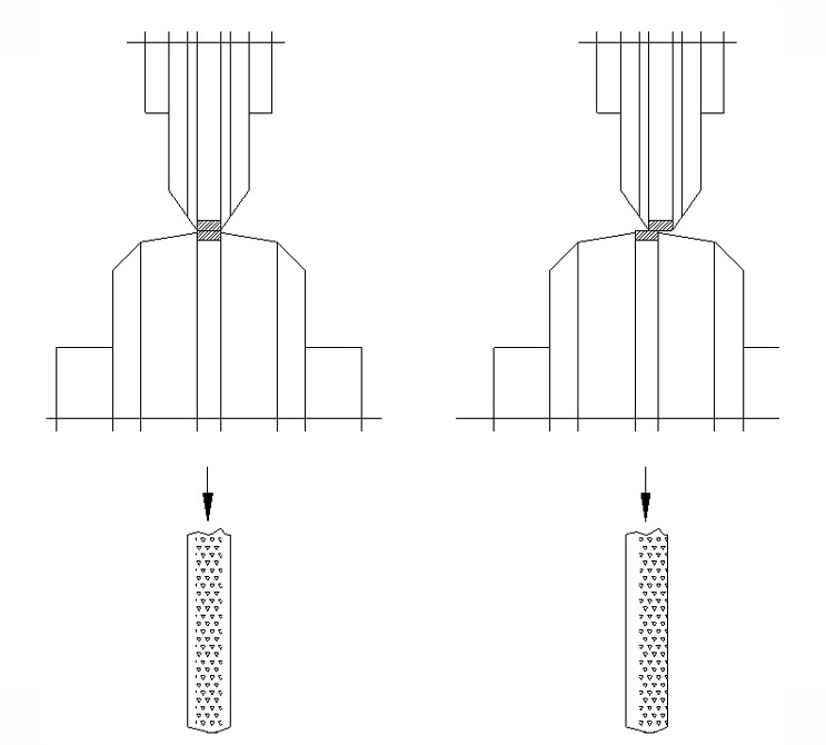
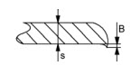
Reference for thickness of the welding seam is related to thickness of material (this value is variable, depending on the overlap of the welding seam, material as hardness and tin coating, welding pressure, welding current and welding frequency).

T = S x 1.75
T = thickness of the welding seam
S = thickness of tin plate

Example:

T = 0.15 x1.75 = 0.2625 mm


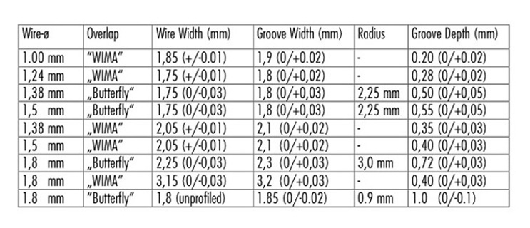
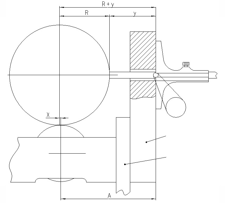
Necking tool tolerance

D = S+W+L+P+E (mm)
D = difference between inside/outside diameter of necking tool
S = thickness of tin plate
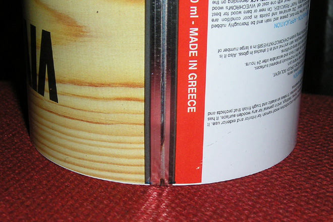
W = thickness of welding seam measured by micrometer (we should measure beginning, middle and end of the welding seam)
L = thickness of outside lacquer stripe 0,02 mm
P = thickness of inside powder stripe 0,07 mm
E = extra space (0.05 mm)

Example:

D = 0.15 + 0.26 + 0,02 + 0,07 + 0.05 = 0.55 mm
S = 0.15 mm / W = 0.26 mm / L = 0,02 mm / P = 0,07 mm / E = 0.05 mm


Check these two PDF documents:

Use this Excel-Form for your calculation.

  • H – grain means rolling direction parallel to the welded seam
  • C – grain means rolling direction crosswise to the welded seam

  • Empty the water tank. On 2-circuit cooling unit only cold water tank has to be emptied.
  • Blow off one by one each cooling circuit in the welder. This allows to empty each circuit separately. If your welder has a 2-circuit cooling system only the circuit for the lower and upper weld roll has to be emptied.
  • Change the filter cartridge and clean the filter housing inside.
  • Fill the tank with water only, open main valve Y14, and run the system for at least one hour to flush rests of old emulsion out.
  • Empty the water tank again and clean again if necessary.
  • Fill the water tank with water (or distilled water if requested), and mix the PowerRoll™ coolant H1 in with 8 percent.


We recommend following maintenance procedures:

  • Change the filter cartridge monthly.
  • Change the cooling emulsion yearly. Use the PowerRoll™ cooling system cleaner at any time you change the emulsion.
  • Use the PowerRoll™ cooling system decalcer after around 5 years.


Order numbers:

  • PowerRoll™ coolant H1 (food grade), 7 Liter, 011494
  • PowerRoll™ cooling system cleaner H1 (food grade), 10 Liter, 011495
  • PowerRoll™ cooling system decalcer, 25 kg, 011496
  • Filter cartridge 50 µm, 002446


Safety data sheets see below:

PowerROLL coolant

PowerROLL Coolant System Cleaner H1

PowerROLL Coolant System Decalcer

Possible cause:

  • insufficient cooling
    • clean cooling circuit
    • change cooling additive / lubricant in the chiller
    • clean or change main- and micro-filter in cooling system (see pictures below)
        
  • Check insulation
    • feel hot spots in the entire secondary circuit by hand or use IR camera if available.
  • Check Z-guide for broken parts (nosepiece or main Z – bar or, depending on welder type, intermediate Z-bar)


Possible cause:

  • LED on the converter does not light up!
    • Lenze frequency converter defect
  • If LED is red, check error code with the keypad.


NOTE:
 In case you have to replace the converter, make sure you load the default parameter setting. All the latest models, do have the parameter setting in the electrical scheme – if you do not have the parameter, contact Can Man by filling out a ticket in the support section on our website.
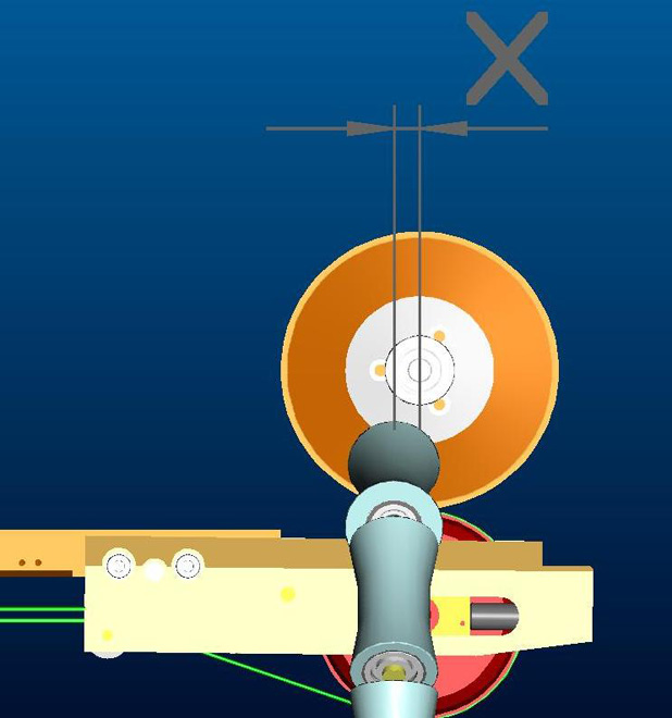
Possible cause:
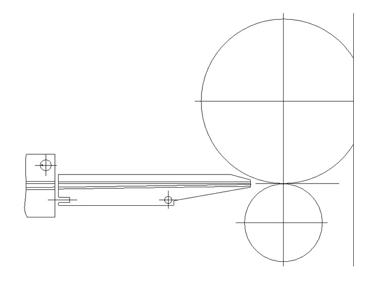
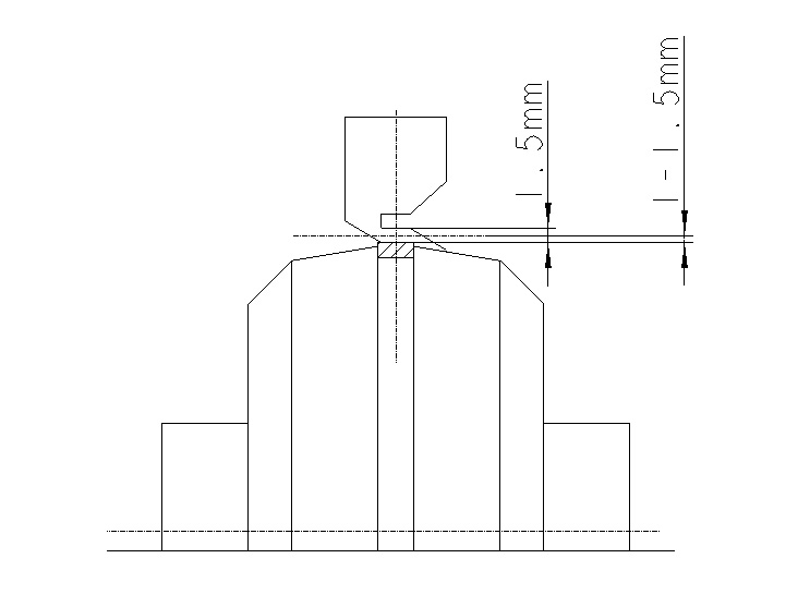
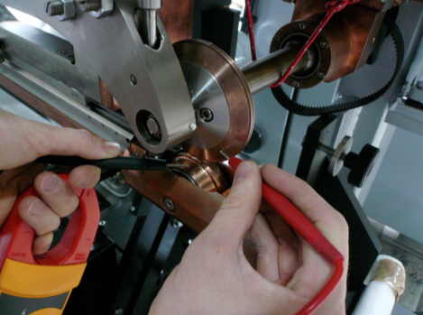
The upper pendulum roller might be not leveled properly. When regrooving the upper disc for example 0.50 mm in diameter, the height of the pendulum rollerhead must be reduced 0.25 mm. This can be done by the M10 screw on the back side.

See also in the manual X1 how to reset the upper pendulum rollerhead.

NOTE: The description manual is based on a CM X1 welder, but it works very similar for our other welders.

ATTENTION: Do not touch the red marked screws!

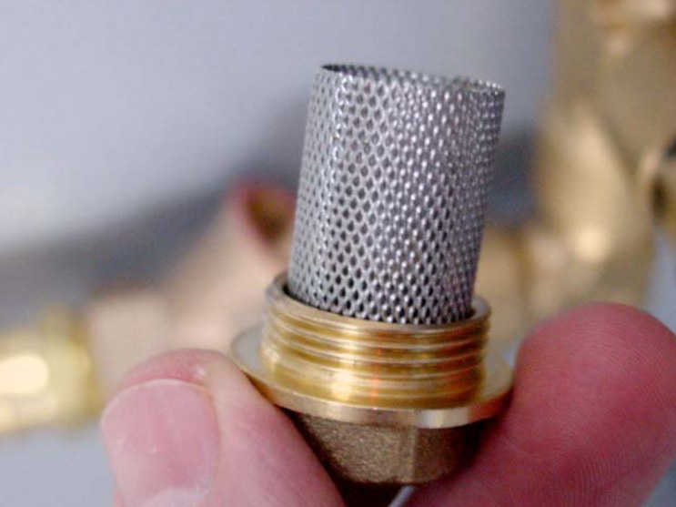
Your cooling system has to be checked and / or one or more circuits need to be cleaned.
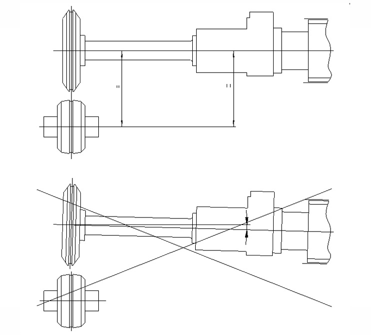
Explanation:
If the temperature difference exceeds a certain value, mechanical mis-alignments may occur which can affect the welding geometry. Obviously it is not the same when a welder is cold (start of production) and hot (after up to1h of production).

NOTE: With Can Man TempGUARD™ system, this can not happen anymore.

  1. Measure the overlap by reducing the welding current until the sheet edges can be broken apart to check, where the overlap is incorrect. NOTE: Machines with a PACEMAKER™ do have a „overlap check“ in the menu!
  2. Check the blank cutting.
  3. Check the condition to the nose piece (even maybe the Z-bar).
  4. Check the „clearance“ of the calibration crown roller (also called hour glass or diabolo rollers), with special attention to the upper ones.
  5. Check the position of the exit conveyor (weld a can without the conveyor and see the difference).
  6. Check whether the idler wheel in front of the lower welding roll is in correct position, or whether the circlip is missing (Xplane only)!

If you still couldn’t resolve the problem, read more here.
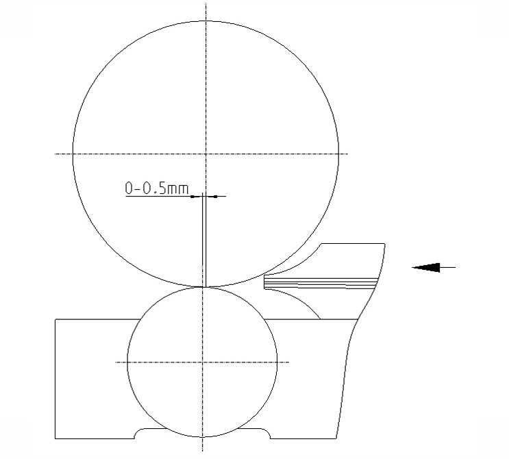
  1. Remove welding pressure and check if deviation of upper (outer) rollerhead (in most machines the pendulum rollerhead) is working properly (free of any mechanical friction or resistance)!
  2. Follow 1. and check „copper belts“ (the flexible power conductors between the rollerhead and the upper bus bar) and that they are not give mechanical resistance (counterforce) to the welding pressure.
  3. Following 1. and make sure that the „lift“ of the upper rollhead is not disabling the welding pressure to be fully obtained to the lower welding roll. This can happen if the both welding roller diam. are smaller than allowed.
  4. Finally check, ideally with a „tension spring balance“, the actual welding force (usually it should be within 40–45 daN)
  1. Change welding frequency (use Can Man PACEMAKER™)
  2. Change to another type of sheet and / or tin coating and monitor the difference.
  3. Make a „screw check“, especially of the secondary power circuit and the z-bar assembly.
  4. Use another overlap
  5. Check if any of the welding roller bearing have to much clearance (change them if so).
  6. Check the condition of the pendulum rollerhead.
  7. Check proper function of welding pressure assembly (see also „problems with welding pressure“).
  8. Check welding geometry in general.

Possible cause:

  1. It might be that you‘ve changed the type of tinplate (hardness or tinlayer).
  2. It might be that you have changed the welding frequency.
  3. If it appears a problem and you need help follow:
    1. I have too many „splattering“ in my welder!
    2. How to check welding pressure assembly?

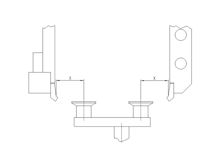
According to the drawing below.

The gap between the cans is not constant (see picture below).

See also following FAQ-article Why can’t I keep the distance from can to can constant?

  1. Check blanc cutting tolerances  and in particular dimension h
  2. Check clearance (wear) of final canbody pushing system.
  3. Check calibration crown adjustment.
  4. Check blanc cutting tolerances and in particular dimension A on a series of sheets (3-7 sheets depending how many knifes are cutting dim. A on your slitter).
  5. Check the speed of the exit conveyor belt(s), which need(s) to be constant and in any case 2 – 5% faster than the actual welding speed.
  1. Check calibration crown adjustment, it is probably to loose.
  2. If 1. is checked with mandrel and you still have the same effect follow What to do when the overlap is too big in the beginning and / or too big in the end of each canbody.

Possible causes:

  • Check the blank cutting tolerances and blank squareness.
  • Adjust the rollformer (roller shaft clearance and spring pressure) according to the manual.
  • Control if there is a high difference in the tin plate hardness, by rollforming 10 bodies without welding. Put them on the floor in line and compare the difference in the rollforming overlap.
  • Check if the destacking process is going well. Make sure the tin plate is guided tight, and the separating air is positioned well.
  • Control the timing of the tin plate transport in between two transport fingers.
  • Make sure that the guidance channel is properly adjusted. The intersection to the precalibration of the calibration crown is most important.
  • Check the position of each (inside and outside!) transport finger compared to rollformed canbody.
  • Check the offset of each finger pair itself. Move the canbody slowly forward (X1 and X6 by slow mode function) and observe eventual shaking of the canbody until the welding point.
  • If a third finger exists: The third finger must be 0.5 mm behind the upper main pusher fingers!
  • Reset the calibration crown completely. Make sure that each precalibration roller is turning easily! If needed lubricate their shafts slightly and clean the roller afterwards. Make sure that these rollers are as close as possible to each other!
  • Measure the speed of the flat belt in the calibration crown:
    The speed must be absolutely identical with the copper wire speed!
  • Measure the overtravel: Short can heights shall have 1 mm overtravel.
  • The center of the diabolo roller (equal to the center of calibration crown) shall be 1–2 mm before the welding center.

X1

950 mm

X8

1020 mm

CM15

1100 mm

CM16

950 mm

CM17

1050 mm

CM20

1250 mm

CM21 WIMA

1000 mm


Please note that those are minimum heights!

For more detailed dimensions, see products page > technical data > Layouts


Check for proper adjustment and alignment of separator-notches, rest bars and sucker bar.

  1. Switch off the main switch Q1 of the machine.
  2. Wait around 10min before you do anything on the wiring of the pacemaker! The capacitors need that time to discharge!!!
  3. Disconnect both welding cables from Pacemaker.
  4. Measure the resistant of both cable to earth. If the value is very low maybe the transformer primary side have short circuit to earth or the cables are damaged and make some contact to earth. If it looks ok (endless or very high resistant) go to point 5.
  5. Take the welding copper wire completely out of welder.
  6. Control that pendulum roller head is lift up. Put a carton or another insulating material between both welding rollers to make sure that you don’t have any contact between the rollers.
  7. Connect an external cable 230VAC (phase and neutral) to the welding cables, which you have removed on pacemaker before. Use for this external supply a 10A fuse breaker to protect the supply in case of a short circuit of welding transformer. (Take a look to picture on point 3)
  8. Before you switch on the external supply check again:
    – Wire removed?
    – Pendelum rollerhead lift up and isolation between welding rollers?
  9. Now switch on the external supply. If the 10A fuse breaker does not trip it is a good sign and it doesn’t look like short circuit of welding transformer.
  10. To control the output of welding transformer you can measure the voltage between the welding rolls (VAC). The measured voltage is depending on the type of welding transformer. If you change the transformer step this value has also to change. Check the output voltage of each step. Don’t worry if you measure only around 5VAC, the output voltage of welding transformer is a low voltage.

Before you change the transformer step switch off first the external supply!!!


Download PDF english

Download PDF chinese

Report all steps, new or different settings, and old and new production parameters (can size, cpm, weld speed, weld current, weld frequency, current wave-form and transformer step) for an easier overview and follow-up ! (www.canman.ch /Open new ticket and add your document)

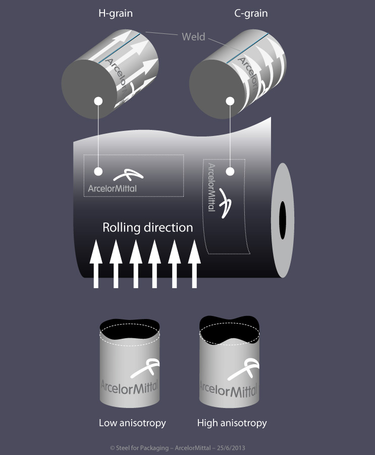
Note on which tin-plate parameters (thickness, hardness, tin coating inside / outside, rolling direction, BA or CA, supplier, printed or not) such faults occur, and on which tin-plates not !

Basic parameters & settings to be checked first

  1. Tin-plates must be cutted within the allowed tolerances:
    • Measure the tin-plates and report if out of tolerance!
    • Follow sheet „blank-cutting tolerances“! (www.canman.ch/SUPPORT/Canmaking/002)
    • Are all tin-plate parameter clear and noted: Thickness, hardness, tin coating in- and outside, rolling direction, BA or CA, supplier, printed or not
  2. Can-bodies must be correctly rollformed:
    • Not conical and best roundness must be reached!
    • Overlap of both tin-plates edges:
      • ø 52 ~ 5 mm
      • ø 99 ~ 15 mm
      • ø 153 ~ 30 mm
      • ø 284 ~ 60 mm
  3. The copper wire must be correctly profiled and the surface not damaged:
    • The width of the profiled copper wire shall always be 0.05 mm smaller than the profile-groove in the weld rollers!
    • Measure the width of the profiled copper wire within around half a meter on several position, and note the variations. Maximum difference of 0.05 mm is allowed. If you measure more, check the concentricity of the profiling rings.
    • Change the copper wire profiling rings or idler/guide wheels if the surface of the copper wire shows a damage.
  4. Both weld rolls must be regrooved after its regular groove life-span:
    • To avoid unexpected heavy weld faults, it is recommended to implement the total piece-counter and the regrooving interval into the production order!
    • As an example:
      • Upper weld disc ø 90 mm to be regrooved after 3 mio cans (interval depends on, type of welder, type of weld roll and welding speed).
      • Lower weld roll ø 62 mm to be regrooved after 2 mio cans.
      • Example: Total piece counter at production start at 28 mio welded can bodies, upper weld disc has been regrooved at 25 mio, therefore to be regrooved now! Lower weld roll regrooved at 27.5 mio, therefore to be regrooved at 29.5 mio.
    • After every regrooving, weld roll and / or z-bar must be repositioned: Use the correct tools to reset the lower weld roll and/or nose-piece, and the upper welding roller!
  5. The z-bar must be clean in and outside – and not worn -, calibration crown must be clean, and all pre-calibration rollers shall turn easily:
    • A dirty z-bar may not be well insulated, therefore the risk of wear is higher and the weld current is flowing over z-bar and tin-plate to the weld center!
    • Note: The insulation of the secondary circuit should be controlled yearly!
    • Non-turning pre-calibration rollers can create body-offset and inconstant can gap!
  6. The calibration crown center must be correctly positioned to the weld center:
    • The center of the crown must stay between 3 – 0.5 mm before the center of the lower weld roll (in weld direction seen).
  7. The position and speed of the exit conveyor (all conveyors which transport the can body out of the weld center) must be aligned perfectly.
    • Both belts of any V-Shape conveyor need to have a gap of 0.3 – 0.5 mm to the can body. If available use a setting mandrel instead of a can body. The alignment of the conveyor must be absolutely parallel to the weld direction!
    • The gap between two can bodies on the exit conveyor should not be higher than10 – 20 mm! (if can gap is 1.0 – 3.0; see „can gap“ in point 12.)
    • A driven diabolo roller / bottom conveyor after the diabolo rollers must run the same speed like the copper wire!
  8. Both tin-layers must be centered and parallel to the copper wire:
    • That means that all mechanical settings are correct!
  9. The copper wire tension and elongation must be correct:
    • Make sure that the air-pressures for the pneumatical cylinders are set correctly, or the copper wire is in the right groove of the wire drive disc (Soudronic m/c’s only).
    • Measure the copper wire elongation after the lower weld roll, or after the weld roll before the wire chopper: Elongation varies under normal conditions between 0 – 4 % of the can body height.
    • A sufficient copper wire tension is important to avoid a slipping copper wire on the weld rolls!
  10. The can body overtravel must fit:
    • Set the overtravel according manual / scale on the transport carriage!
    • Measure how many mm the can body will be pushed over the center of the weld rolls.
  11. The welding pressure must be set correctly:
    • Welding pressure for Wima welders vary between 35 and 50 kg / daN. Start with ~ 45 kg / daN (if needed check the manual to convert in bar).
    • 50 Hz Wima welders using welding pressure between 35 – 50 kg/daN as well.
  12. The welded overlap must be correct, and on beginning and end within allowed tolerances:
    • Correct welded overlap depending on z-bar:
      • Z-bar of 0.3 mm results in a welded overlap of 0.4 – 0.5 mm
      • Z-bar of 0.4 mm results in a welded overlap of 0.5 – 0.6 mm
      • Z-bar of 0.6 mm results in a welded overlap of 0.6 – 0.7 mm
      • Z-bar of 0.8 mm results in a welded overlap of 0.8 – 0.9 mm
    • If the overlap is not correct, adjust until overlap is correct:
      • Reset the calibration crown if needed with the mandrel. The diabolo-rollers should not have any radial-play!
      • Adjust the overlap according manual.
    • Once the overlap has been set, double check and set the can gap. Increasing the overlap will reduce the can gap, decreasing the overlap will increase the can gap.
    • Weld around 5 cans and measure the gap between the tin-layers. A good can gap measures between 1.0 – 3.0 mm (depending on the can body format). Any variation should be within 0 – 1.0 mm.
  13. The weld current frequency must fit:
    • Welders with a static frequency inverter should have a welding spot length between 0.6 – 1.2 mm.
    • A welder without static frequency inverter should be operated between 8 – 12 m/min. Reducing the welding speed does decrease the welding spot length.
    • The welding spot length should always be as long as possible (by reducing the frequency) to reduce energy and heat in the welding seam and in the welder to a minimum.
    • Main target must be a flexible and smooth welding seam!
  14. The main weld current must be set correctly!
    • How to do:
      • Reduce weld current until cold weld zones appear. Tear-off test must be done at an angle of 30 – 45°, means try to pull-off the top tin plate edge. To be done from each side. Note the weld current value!
      • Increase weld current until hot weld appears. Tear-off test must be done at an angle of 0°, means pull-off the seam only and find out when the seam starts to become fragile. Note the weld current value!
      • Add 2/3 of the weld current difference between cold and hot weld seam to the cold weld seam value, and start the production!
    • Set beginning and end time and beginning and end current!
    • Note: If the welder is running with triangle wave-form, make sure the duty-cycle is between 80 – 90 %. If the welder is running with sine wave-form, make sure the right transformer step has been choosen! Contact us if you are not sure.
  15. The seam-extrusion inside and outside must be equal!
    • If the seam extrusion is bigger inside, reduce the height of the calibration crown. If the seam extrusion is bigger outside, increase the height of the calibration crown.


Checklist to Avoid Micro Leaks

Micro leaks can occur within the seam and beside the seam – especially on cold-formed areas like necking, beading, flanging or seaming -, even if all above mentioned basic parameters & settings seems to be correct.

Micro leaks can have various sources: Wrong settings on the welder, tin-plate parameters which support such faults, worn or wrong machineries in the downline, or tin-plate parameters which do not fit to beader, necker, flanger and seamer.

For a better visual understanding put the faulty-can bodies in a water bath, and inspect the leaking area by a microscope. Store the pictures if possible!

  1. Make sure that necker, flanger, beader and seamer are in good condition, and do not stress the weld seam more than needed.
    • For further information check the manuals (check the tin-plate specifications range) or contact the supplier!
  2. Try to weld different tin-plates to understand which tin-plate parameter can be produced without such faults.
    • Rolling-direction parallel to weld seam can increase the occurrence of micro-leaks!
  3. Micro-leaks in and near the seam can be reduced by changing the energy in each welding spot:
    • Reduce the welding frequency within the possible range (see point 13. in above checklist), and set the main weld current again (see point 14. in above checklist). The production cycle (cpm) must probably be reduced to reach a good weld seam. Produce a certain number of cans and test them.
    • Increase the welding frequency within the possible range, and set the current again. Produce a certain number of cans and test them.
    • Reduce the welding pressure to max 45 kg / daN, and set the main weld current again (see point 14. in above checklist). Produce a certain number of cans and test them.
    • Reduce the welded overlap by around 0.10 mm, and set the main weld current (see point 14. in above checklist). Produce a certain number of cans and test them.


Checklist to Avoid Flange-Cracks

Flange cracks can occur at the beginning and the end of the seam, even if all above mentioned basic parameters & settings seems to be correct.

Flange cracks can have various sources: Wrong settings on the welder, tin-plate parameters – for instant parallel rolling direction – which support such faults, worn or wrong flanger in the downline, or tin-plate parameters which do not fit to the flanger and or seamer.

For a better visual understanding put the faulty-can bodies in a water bath, and inspect the leaking area by a microscope. Store the pictures if possible!

  1. Make sure that flanger and seamer are in good condition, and do not stress the weld seam more than needed:
    • For further information check the manuals (check the tin-plate specifications range) or contact the supplier!
  2. Try to weld different tin-plates to understand which tin-plate parameter can be produced without such faults:
    • Rolling-direction parallel to weld seam will increase flange cracks, because the seam cracks in line with the rolling direction!
    • Weld tin-plates with cross rolling direction and test them.
  3. Flange cracks can be reduced by changing the energy in each welding spot:
    • Reduce the welding frequency within the possible range (see point 13. in above checklist), and set the main weld current again (see point 14. in above checklist). The production cycle (cpm) must probably be reduced to reach a good weld seam. Produce a certain number of cans and test them.
    • Increase the welding frequency within the possible range, and set the current again. Produce a certain number of cans and test them.
    • Reduce the welding pressure to max 45 kg / daN, and set the main weld current again (see point 14. in above checklist). Produce a certain number of cans and test them.
    • Reduce the welded overlap by around 0.10 mm, and set the main weld current (see point 14. in above checklist). Produce a certain number of cans and test them.
    • Activate the current reduction on the begin and end to reduce the heat in the first few welding spots.
  4. If above listed does not help, some theoretically wrong settings could help:
    • Increase the can gap to have completely different welded begin and end. Produce a certain number of cans and test them, and set back if it didn’t help!
    • Set a slight can-body offset, to bring the current different into the tin-plate. Produce a certain number of cans and test them, and set back if it didn’t help!
All Can Man content is now also available on the Soudronic Group website.
Where do you want to continue your journey?
All Can Man content is now also available on the Soudronic Group website.
Where do you want to continue your journey?