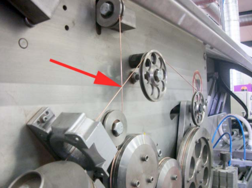
NOTE: Make sure that the wire is not touching anywhere. Only a perfectly set and maintained canbody welder, can assure perfect welding! A weld monitor is a pure “measuring instrument”.
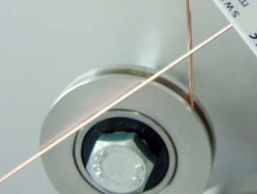
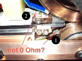
Check this specific wire crossing (red arrow). The wire might touch each other here!
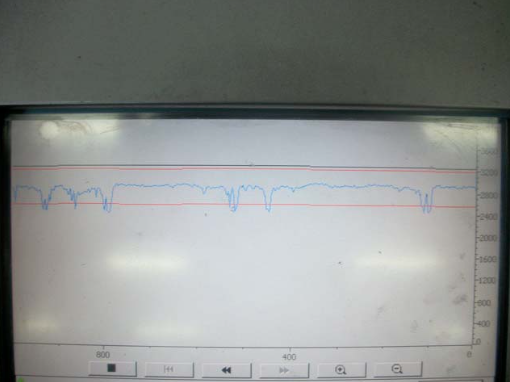
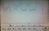
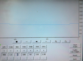
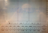
Switch OFF the QM eject function and record the curve.

Curve not stable!
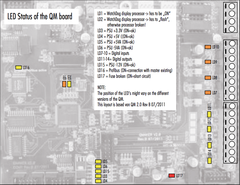
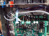
Check the connection from the voltage pickup to the Qualimaker board.
Possible cause:
Possible cause:
Cause 1:
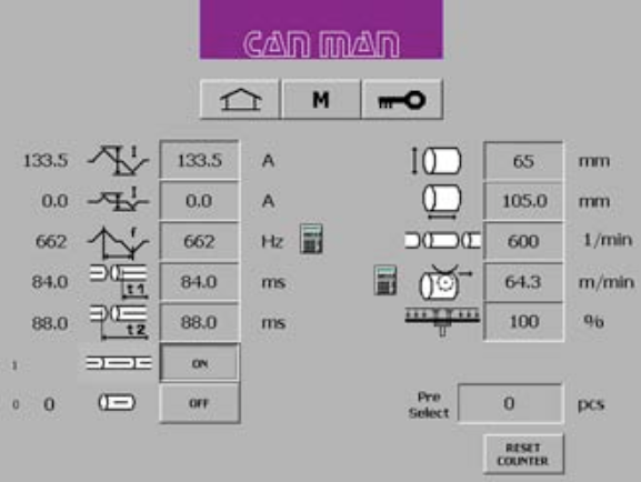
The setting of t1 and t2 is wrong. If the timing is wrong the PM cannot execute the signal, which is necessary to memorize the canbodies in the reject unit and to start the record of the graph.
Setting of t1 and t2:
t1 defines the starting point for the reduced current time window. ![]()
t2 is the time, where the reduced current windows ends. t2–t1= thus is the timespan for the reduced current, therefore t2 > t1! ![]()
NOTE:
The value of t2 and t1 needs to be smaller as the cycle of one single can.
For example:
A production of 300/min. corresponds to a cycle time of 200 ms/can. Production of 600/min. corresponds to 100ms/can.
NOTE:
For a more detailed explanation of timing t1 and t2, consult your manual book 2, chapter 5.6.5. “Setting of Parameter t1 & t2 for reduced Current and Overlap Check“.
Cause 2:
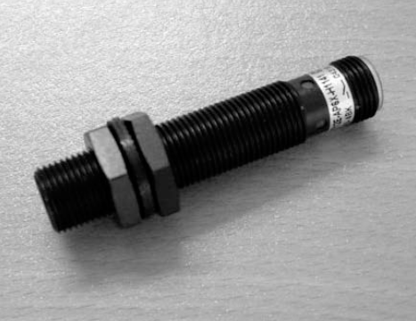
Check the inductive proximity switch B64 at the final pusher unit for function, operating distance and defect.
B64
Final pusher (Synchrostar II): Sensor B64.
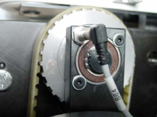
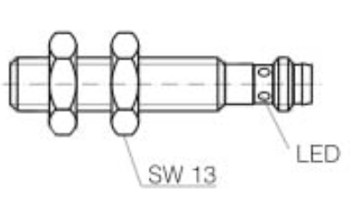
Description:
Inductive proximity sensor for embeddable mounting.
Polarity: PNP
Output: NO. or NC.
Operating distance: 2mm
Cause 3:
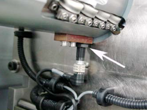
Check the tool switch B6 in the calibration tool for function, operating distance and defect.
B6
The position of the welding sensor B6, can be almost flush. Just make sure that you do not get scratches on the canbodies.
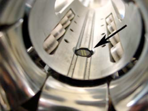
The height of the sensor can be adjusted here (see arrow).
Inductive Sensor (magnetic field resistant)
Mounting mode: flush
Function principle: inductive/normally open Rated operating distance: 3 mm