The motherboard battery is a CR2032 lithium-metal cell. It is used to supply power to the clock integrated on the motherboard. If the battery is depleted or missing, the date and time are displayed incorrectly. Recommendation for replacement interval is 5 years.
For instructions on how to replace the battery use the download link below. You will also find the correct battery type there.
All Beckhoff control units are equipped with a UPS to ensure the proper shutdown of the control IPC. However, this only works if the battery is in perfect condition to prevent data loss and ensure the flawless operation of the control system. The battery module for the UPS must be replaced every 5 years.
To order a new battery please contact spares.canman@soudronic.com.
For instructions on how to replace the battery use the download link below. You will also find the correct order number there.
Possible Causes & Resolutions:
Problem:
Circuit breaker Q5 trips when the machine is switched on or during production.
Possible Causes or Resolutions:
Problem:
All drives are starting correctly, but the vacuum and welding current are not active.
Possible Causes & Resolutions:
Problem:
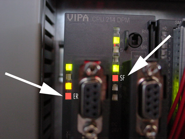
Some Beckhoff i/o terminals are not active and status LEDs are off, control does not respond to commands.
Possible Causes & Resolutions:
Problem:
Possible Causes & Resolutions:
Problem:
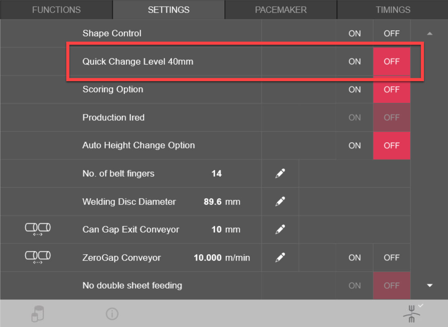
After main switch off and on again, HMI piece counter values and settings are lost or old recipes are loaded.
Possible Causes & Resolutions:
Problem:
During production, the error message “over temperature upper current conductor” appears. This means that the cooling is no longer sufficient to keep the upper current conductor constantly below 40 degrees Celsius.
Possible Causes & Resolutions:
If the cooling unit is working properly (temperature and pressure is OK) and no flow switches are giving an error, then contamination is most likely the cause of the problem.
Clean the cooling circuit, especially the cold-water circuit in this case, including the cooling unit. Check the water level in the cooling unit and top up if necessary and replace lubricant (if PowerROLL – coolant or DISCON is used) and clean the cooling system as recommended every 6 months.
Problem:
Downstacker motor doesn’t move correctly to the reference position, stops or suddenly changes the direction of rotation. Display of servo controller U16 shows „IMax“ or „P03 trip“.
Possible Causes & Resolutions:
To check:
Problem:
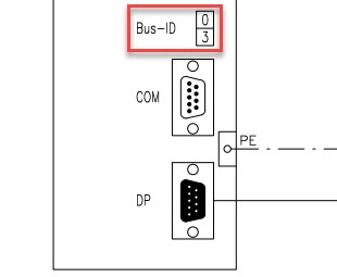
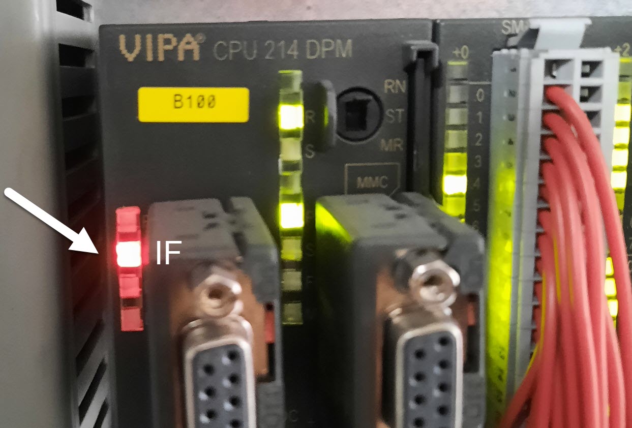
Machine stops and message „Pacemaker: Profibus communication error“ is displayed.
Possible Causes & Resolutions:
Problem:
The HMI cannot be started and the browser shows „NOT FOUND, The requested URL /en/default.htm was not found on this server“.
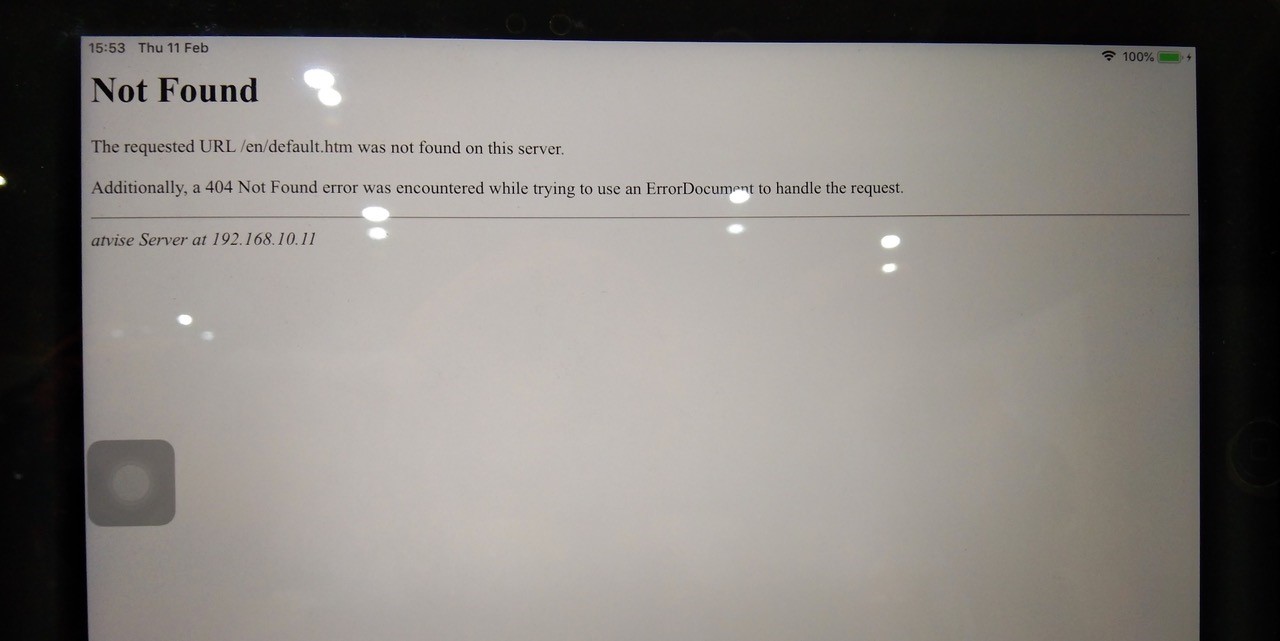
Possible Causes & Resolutions:
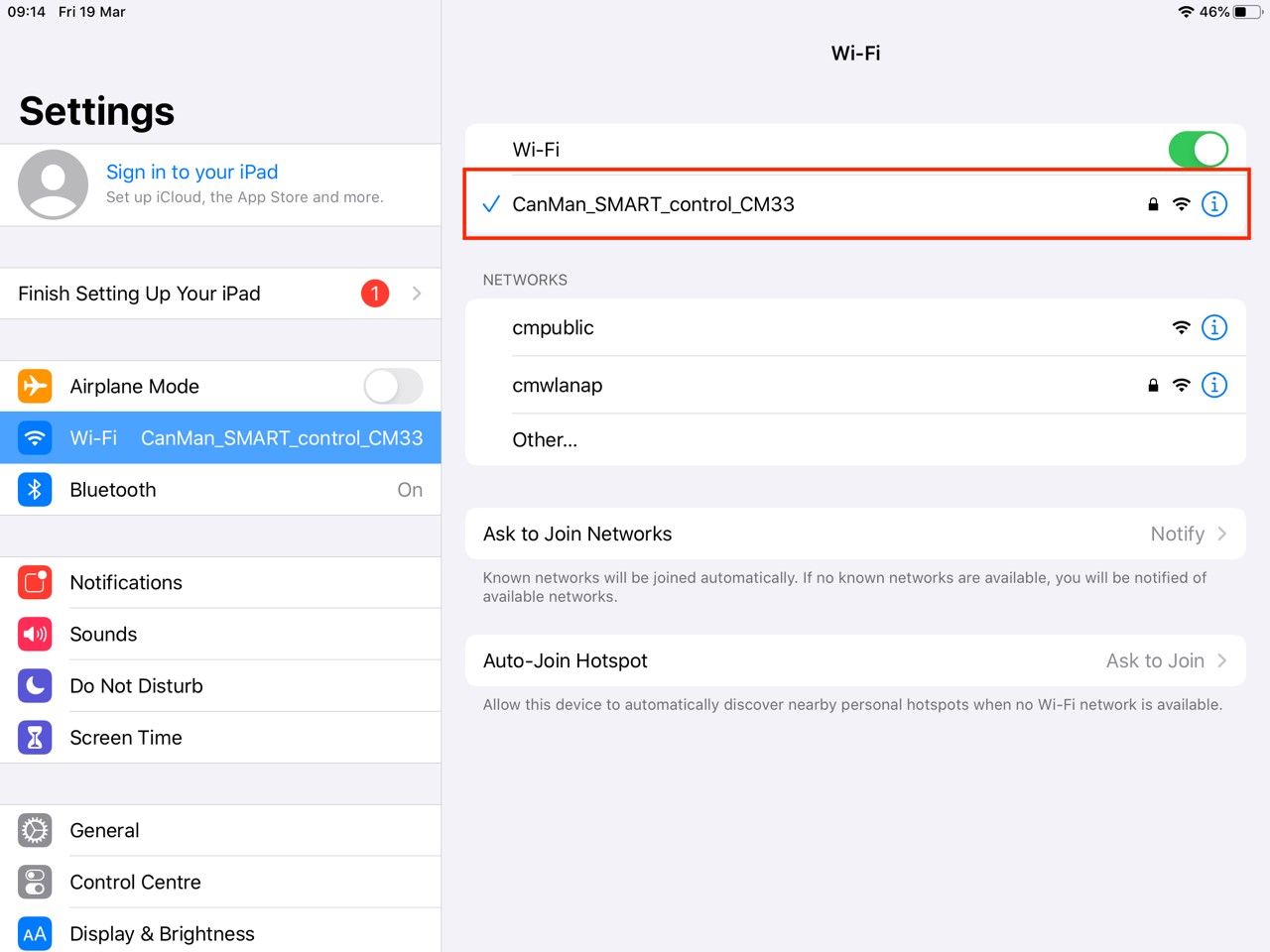
Not connected to Canman Wifi (only for wireless connected iPad’s): Check the wifi settings. Choose Canman wifi and try again.
IPC has not shut down correctly: In this case probably the HMI software can’t start up automatically by restarting the machine.
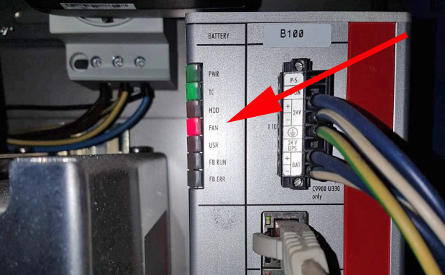
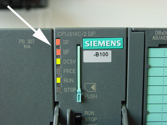
Check the IPC after you switched off the main switch: Normally it will continue to run for at least 30 seconds to shut down correctly. If LED’s of IPC goes off within a few second, the battery of the UPS – unit is dead and needs to be replaced. Contact Canman for online support to restart HMI.
Possible reason:
Problem:
Canbody transport motor doesn’t move correctly to the reference position, or stops, or changes the direction of rotation, or the display of the servo controller U7 shows „IMax“ or „P03 trip“.
Possible Causes & Resolutions:
To check:
Problem:
Possible Causes & Resolutions:
Problem:

Possible Causes & Resolution:
Problem:
Possible causes & resolutions:
Note: If you use a new iPad the icons for the machine type can be produced, when you tap on “Add to home screen“ button.

Problem:
Display shows „Could not activate iPad“
Possible causes & resolutions:
For connecting an alternative display / PC, please have a look at the separate FAQ.
Please follow the below instructions carefully:
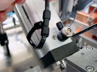
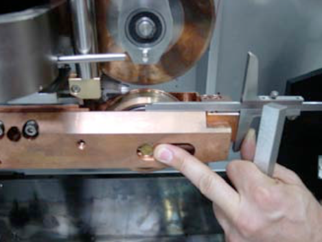
Take off the lower weld roll, unplug the grey water tube ø 10 mm labeled with “àWR” directly at the flow switch S26, and blow into the tube with air pressure. Check the out-going air-pressure at the free hole in the lower weld arm (supply for lower weld roll). If the circuit is free, you feel an equal air pressure (like on the output of the air gun) on your finger tip. If you recently took off the lower weld arm, there might be a problem with one or both o-ring seals between arm and upper bus bar:
Please check them if needed !
Before re-connecting both grey tubes ø 10 mm, blow into one tube again by air-pressure, and feel the equal air-pressure on the other tube by your finger tip. If it’s ok, correctly connect both tubes again.
Problem:
Possible Cause:
Check:

Problem:
iPad does not connect to the machine. Screen remains gray and shows no values.
Possible Causes & Resolutions:
Battery of IPC is empty when:
To Do:
Possible causes:
ATTENTION:
If you have a ceramic Z-bar e.g. X7 welder, please not that the ceramic Z-bar is very fragile.
In case you have to exchange or to replace the Z-bar, never use a hammer or apply excessive force!
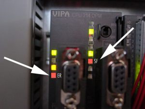
Click here for the status LED’s of the Beckhoff PC and how to access the PC in case of a trouble shooting.
Possible causes:
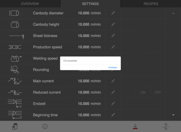
What does this error message mean?
CCD = concurrent connected data variables.
The amount of active CCD is limited. Opening the HMI is using some of the available CCD.
Closing the HMI is releasing the CCD again.
When you repeatedly open and close the browser, the CCD can still be in use and getting into the limitation.
(There is a delay for releasing the CCD when closing the connection).
„If a client wants to subscribe to new data variables while no more CCDs are available, a message “CCD exceeded!” will appear and there will be no communication with these data variables.“
„If a client disconnects from the visu (e.g. browser gets closed), it will take some time until the browser session expires and the CCDs from this client become available once again (session timeout of the scada server: 2 min.).
How to solve a CCD exceeded?
Close alle open browser connection (HMI app) and wait for >2 min.
Now you should be able to open the HMI without error message.
Closing apps on iPads with a home button:
Closing apps on newer iPads without a home button:
How to prevent a CCD exceeded?
Don’t open the HMI in several browser simultaneously.
Don’t repeatedly open and close the HMI in short time.
Don’t repeatedly press reload the HMI in short time.
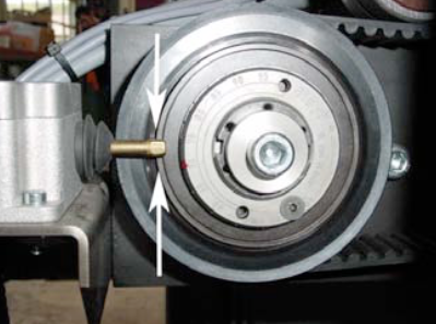
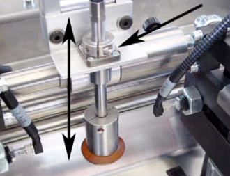
Possible cause:
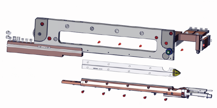
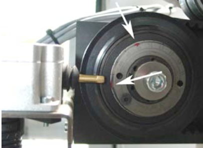
The upper pendulum roller might be not leveled properly. When regrooving the upper disc for example 0.50 mm in diameter, the height of the pendulum rollerhead must be reduced 0.25 mm. This can be done by the M10 screw on the back side.
See also in the manual X1 how to reset the upper pendulum rollerhead.
NOTE: The description manual is based on a CM X1 welder, but it works very similar for our other welders.
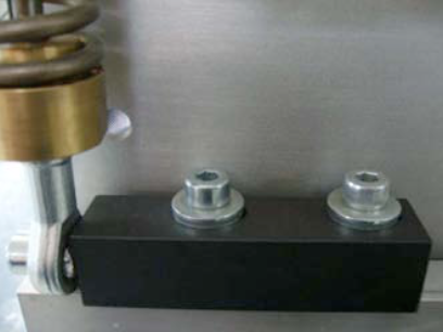
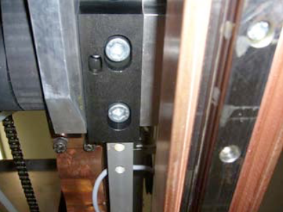
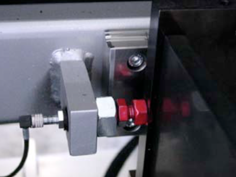
ATTENTION: Do not touch the red marked screws!
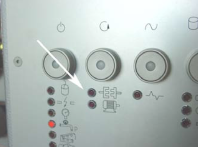
Possible causes:
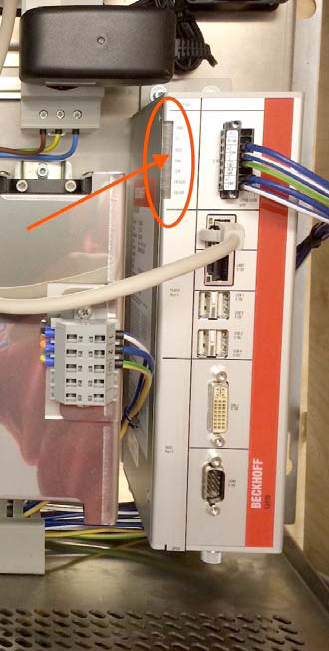
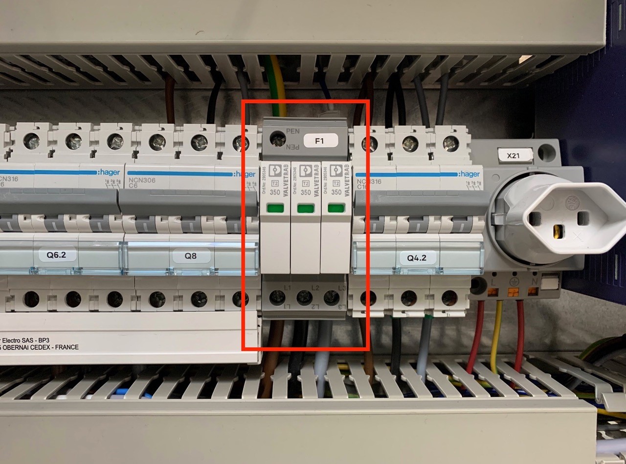
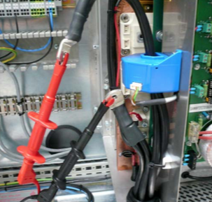
An overvoltage suppressor (or surge suppressor) is an appliance designed to protect electrical devices from voltage spikes. A surge suppressor attempts to regulate the voltage supplied to an electric device by either blocking or by shorting to ground voltages above a safe threshold.
These surge suppressors are built in to the latest Pacemaker models and machine controls (from 2009).
Check, if one or more modules of the surge suppressors are red/defect. Replace the red modules.
Attention!!!
Do not bridge the signalling contacts and run the machine with defective red modules because they no longer protect the system from voltage peaks!!!
If the modules are defective, check the main supply. Measure and check all voltages between the phases and all phases to earth before exchange the modules and restart the machine.
Possible cause:
Before you change the transformer step switch off first the external supply!!!
Download PDF english
Download PDF chinese
Possible cause:
Download PDF here
German instruction: page 52 – 55
English instruction: page 110 – 113
French instruction: page 172 – 175
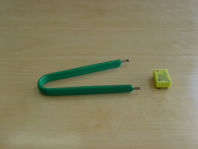
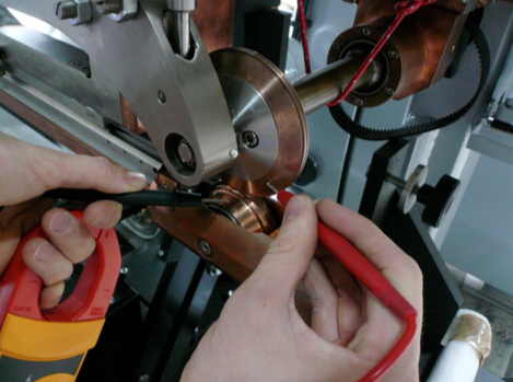
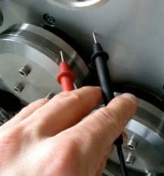
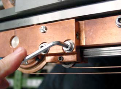
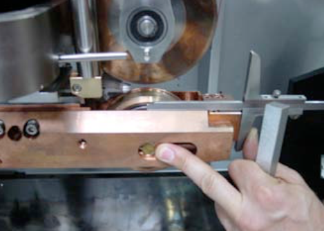
Use a common Ohmmeter, as you can see on the picture.
Measure the resistance between left carbide ring and main aluminum plate.
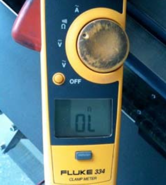
The measuring result on the Ohmmeter must be endless!
Measure the resistance between left carbide ring and main aluminum plate.
The measuring result on the Ohmmeter must be endless!
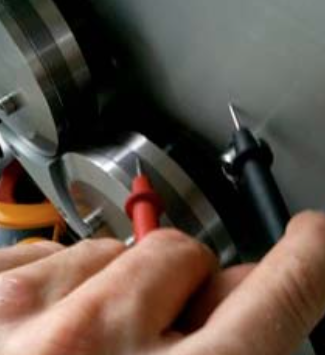
Measure between left and right carbide ring. The result on the Ohmmeter must be endless! This step is to ensure the proper insulation of both rear insulation rings around the taper roller bearings!
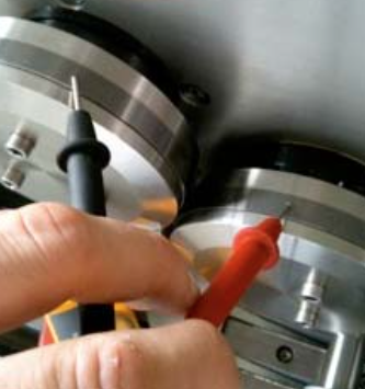
The picture shows the correct measuring result on the screen of the Ohmmeter for all three test points!
Download PDF here
Possible cause:
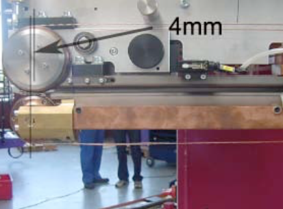
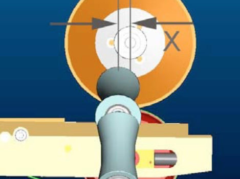
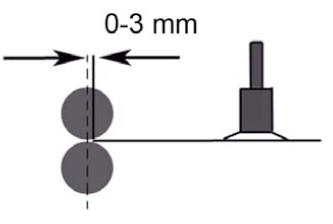
Work: Alignment of the roller head
IMPORTANT:
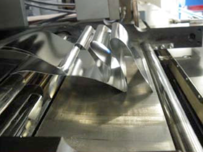
The center of the upper roller head must be approx. 4mm ahead of the center of lower roller head. This setting supports the achievement of accurate overlap during the welding process.
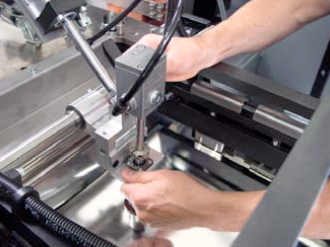
Procedure:
Switch off the air supply, the welding roller heads should touch each other.
Loose the chain tensioner.
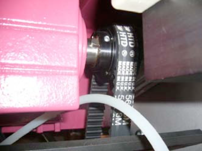
Undo the 4 x M8 screws of the current band
Undo the 4 x M8 screws of the motor to reduce the tension of the timing belt.
Undo the 2 x M8 screws of the oscillator to loose the connection to the welding pressure.
Undo the 2 x M12 screws of the oscillator.
Adjust the oscillator, in order to achieve the offset of 4 mm (see explanation in the first frame).
Tighten the oscillator.
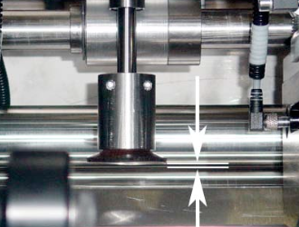
Question: Are both wires lined up accurately? If not, undo the oscillator once more to shift it slightly sideways.
IMPORTANT: Check if the welding roll touches the oscillator. If yes, adjust the welding roll sideways.
The remaining work is, to perform the reverse sequence of the procedure.
Machine basics:
– Overlap 6.0 mm
– Copper wire diameter 1.8 mm – Galvanized metals 0.7 mm
1. Maintenance:
1.1. Make sure the whole Z-bar area (also the inner part) is free of small swarfs, steel dust and other. This little dirt can reduce the function of several isolations, and the weld power starts to become uncontrolled! Sometimes more, sometimes less power could be the negative effect!
1.2. Run one or more metals without current, and feel any slight vibrations / acc – decelerations while moving forward!
2. First, basic adjustment:
2.1. Copper wire profile (width not thickness!) after the profiler must be between 2.20 – 2.25 mm. Use the delivered micro-meter to measure the copper wire, if needed adjust the profiler, see the manual.
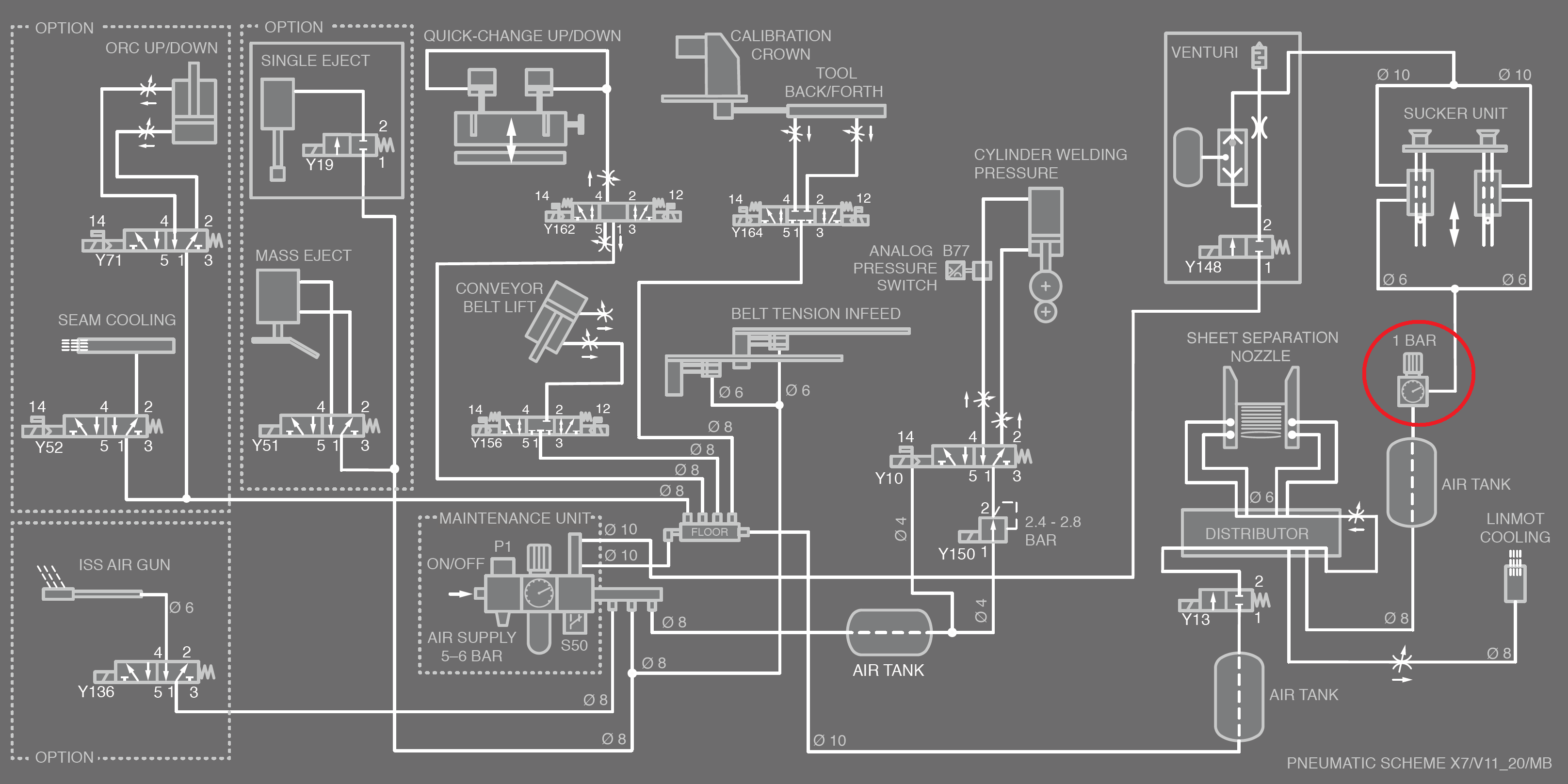
2.2. Wire tension: On the main aluminium plate you see an air regulator. Set the pressure to 3.0 – 3.5 bar by turning the handle on top of air regulator. If the copper wire is running, the wire must be well tensioned. You can imagine, if the copper wire has a low tension, he likes to get welded with the metal. If the tension is to high, then the copper wire like to get stretched, and can break frequently.
2.3. Welding pressure: Close the welding wheels by turning the turn-switch on the panel. Near to the upper welding wheel you see a spring. Close to the spring you see an aluminium welding pressure. The lower end of the spring shows the value on the scale: Should be between 60 – 70 daN.
3. Second adjustment:
3.1. Start and end timing weld power: Both potentiometers should be zero. Weld a sample. Now you should have minimum 1 mm unwelded in the beginning / end. If not, adjust S63 and S64 until you see it. Now we are sure that the copper wire can not get damaged due to burned beginning / end!
3.2. Reduce weld power: Probably the weld power is to high. Reduce, and check if the welding is still enough, or the metals start to break off. Go back to origin value.
3.3. Increase welding pressure: Go up in 5 daN steps, and proof the metals. Target has to be, that the zinc – craters around the welded areas are getting reduced. This means that the metals got melted closer to their contact – point.
3.4. Increase weld speed: Turn the potentiometer 10 by 10 units (not over 30 for galvanized metals!), and weld some metals. Possibly you may adjust S63 and S64 again.
4. Others:
4.1. Two copper wires: If you can not get successful, use two copper wires (control also on the second wire the profile!), and weld some metals. If the wire breaks has stopped, send us more pictures of your last welded metals. Now you can continue your production, while we can rethink next steps to help you.
NOTE:
A minimum of marks will always be left on the canbody, because the CM21 is a semiautomatic welding machine with a clamping system.
But you can minimize the marks on the canbody, we can show you how.
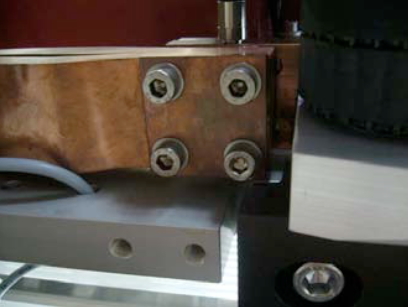
Loose all four allan screws.
Adjust the nose/headpiece through the excenter with a screwdriver and then tighten all screws again.

Possible causes:
=> How to adjust below, have a look at the manual!
Transformer step: 1 (if other is chosen, mention it)
Air supply: min. 4 bar and dry/clean! Check if water is in the tank, if yes, please mention
it, and if the filter is still in.
It may happen that an air regulator is damaged/not working properly, due to
water or dirt.
Copper wire profile: 2.05 +/- 0.03 mm
Welding roller grooves: width 2.10 mm, depth 0.40 mm
Edges should not be sharp, grind them manually!
Welding speed: See display frequency inverter, 50 – 55Hz (10 – 12m/min)
Above 12m/min micro leakages can appear!
Welding pressure: 1.7 – 2.0 bar (35-40 daN/kg)
– Set the ball joints on both central pressure cylinder (piston in top position):
Measure from end of ball joint to the begin of piston, it must be 22 mm or until the steel bar (of pressure link) is laying parallel to the base alu-plate
=> Target: Distance between pressure link rollers and groove of clamp bar around 0.5 mm
– Z-bar must be mounted parallel to top alu-plate
=> Measure with depth gauge left and right!
=> Measure the isolation between Z-bar and top alu-plate!
– Precise guide-bar (underneath Z-bar) must be positioned and mounted parallel to Z-bar => Measure with depth gauge left and right!
– Mount lower weld arm to Z-bar
=> Measure the isolation between Z-bar and lower weld arm
– Mount the lower weld roll, and set the height: Top point of weld roll (incl. copper wire) must be on the same height with center of Z-bar, or bottom side of upper Z-bar groove!
=> Depending on form of can body after welding!
– Move the upper excenter-shaft (rear axle of big alu-block which holds the upper weld roll), until the center of the upper weld roll stays around 1 – 2 mm behind the center of the lower weld roll
=> Helps to keep the overlap!
– Mount the small bearings on to inner and outer little shafts on the Z-bar
=> Lateral play of bearing shall be around 0.1 mm
– Mount the (brown) bottom base-plate onto both precise-carriages
=> Make sure that all 4 pins in the base-plate touch the precise-carriages inside!
– Start to mount the watercooled clamp-bars:
Place the outer / bottom clamp-bar ontop of bearings, move the bar forward and backward, and check whether the bearings are running freely in the groove
– Mount the alu-support between clamp-bar and bottom base-plate, and tight all four M6 screws slightly. Move the carriage forward and backward, and tight the screws step by step.
=> Whenever the clamp-bar is tightened, and the carriage is moving forward and backward, there should no resistance be felt during movement!
– Same procedure with inner bottom clamp-bar. Before lock the rear screws, mount the stainless steel plate on the front end of both bars and make sure that both bars are in line! Do not fully tight the M5 lock-nuts!
– Set the upper front pressure link:
Rear turning point must be free of play, see the assembling drawing for further information
– Tight the center grub screw M8, until they touch the Z-bar slightly
– Measure with depth gauge between front end of pressure link to Z-bar: Result should be 18.2 +/- 0.1 mm. If you have a different measure, change them by moving the grub screws.
– Place the outer upper clamp bar, move both sliding rollers from both pressure links into the groove, and tight both M6 screws on the rear vertical support rail. Measure between clamp bar and Z-bar should be 30.3 mm, see also in the assembling drawing. If not yet, loose the M6 screws and move the support again.
– Same procedure with inner upper clamp-bar.
– Connect the cylinder (piston in top position) wit the upper clamping bar, and adjust the ball joint until the distance between the upper and lower clamping-bar measures 1.0 +0.2/-0.0 mm
– Same setting to be done with the cylinder inside.
– If everything is fine the gap between the clamp bars in the front in and outside is also 1.0 +0.2/0.0 mm
– Finally check the clamping-force efficiency of the inner and outer clamping pairs: Air-pressure between 3 to 4 bars.
– Place a tin plate in the outer inner Z-bar groove, close the bars, and try to pull the tin plate out of groove by hand
=> The force on both sides should be as equal as possible.
Possible cause:
NOTE: There are two type of wire tension systems for the CM16:
Possible cause:
Possible cause /checklist:
Possible cause:
Possible cause:
Important requirements:
Possible problems, if the overlap function does not work!
Remove all eight screws of the upper and lower unit. Then you can take off the front part and replace the profiling rings.

NOTE:
Be careful there are o-rings behind the front part.
In case you do not have the spare profiling rings, we recommend you to order the profiling disc complete, with carbide ring:
order no. 009904 (without cooling) order no. 011123 (with cooling)
depending on your configuration.
http://support.apple.com/kb/TS3281
Symptoms
Your iPhone, iPad, or iPod touch may occasionally stop responding to buttons, switches, or touchscreen input and may exhibit one or more of these symptoms:
Resolution
Troubleshooting touchscreen response
http://support.apple.com/kb/ts1827
Symptoms
Use this article to troubleshoot the following Multi-Touch display (or touchscreen) response issues:
Resolution
If your device is experiencing any of the symptoms listed above, try the following steps:
Additional Information
Tip: To isolate an issue related to a portion of the Multi-Touch display, follow these steps:
Possible cause:
Possible cause:
Problem:
The waterflow LED is on during start up of production / The waterflow LED do switch off only if the button “production on” is pushed for a long time.
Possible cause:
Possible causes:
Possible cause:
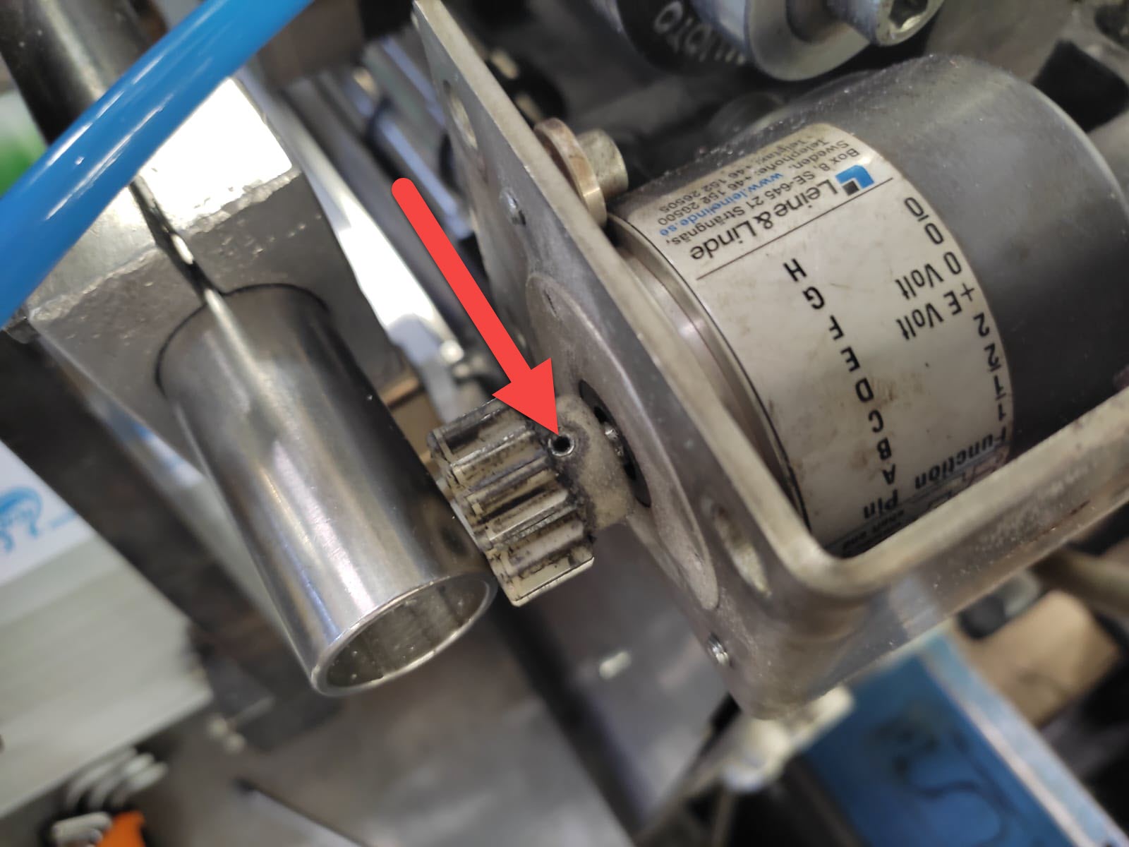
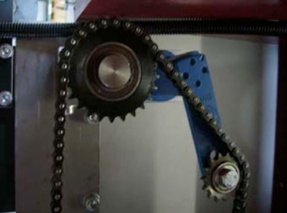
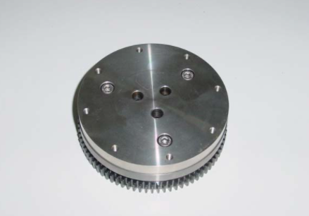
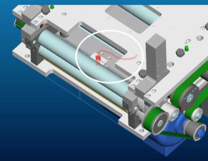
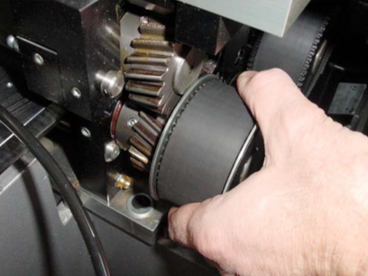
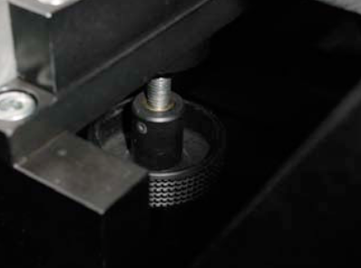
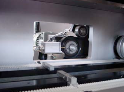
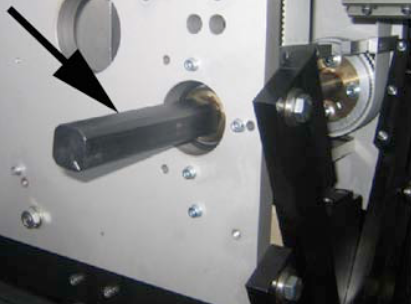
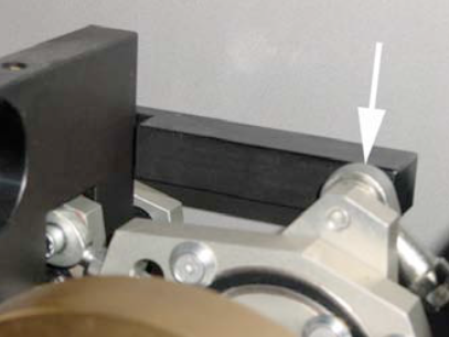
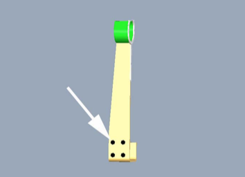
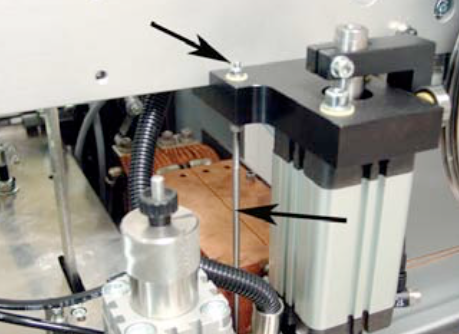
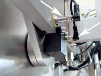
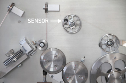
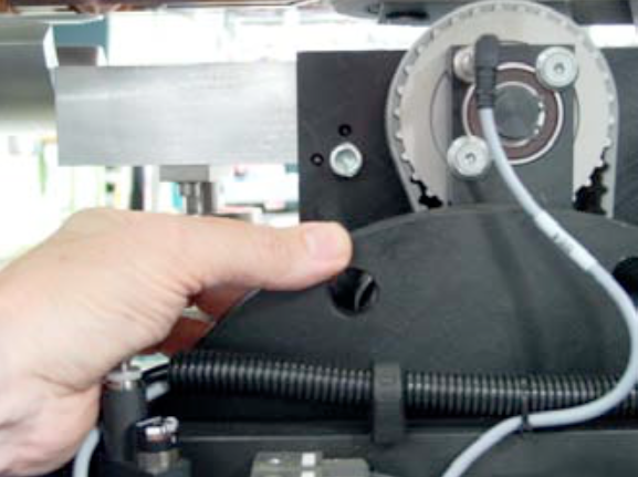
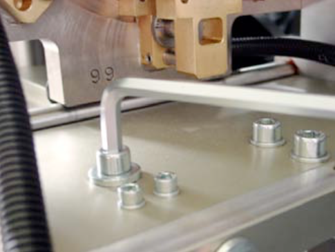
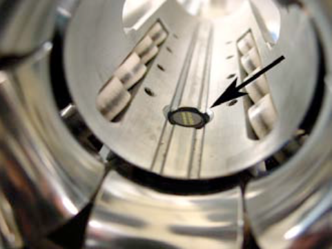
The encoder signal for the production speed of the inverter U7 is coming from a external encoder mounted on the downstacker. On the shaft of this encoder there is a small white plastic gear wheel mounted. Please check the screw of this wheel, it might not be fixed well.
> See picture below to find the encoder.

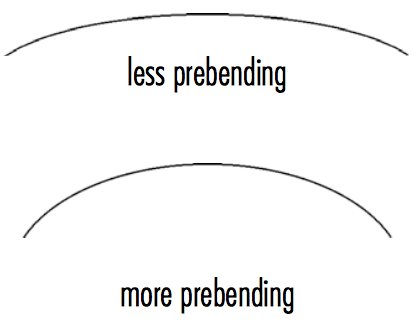
This is the result of a wrong flexer setting!
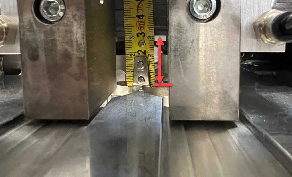
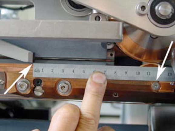
Open the rollformer and you undo the screw on the right handside of the “Flexer”. ![]()
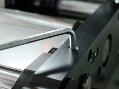
Measure with a ruler the actual position of the flexing wedge.
On the other side of the flexer, you can alter the position of flexer with the M8 screw. Choose a lower position for less flexing.
NOTE:
With more flexing the sheet comes out of the flexer station with less prebending.
If you do less flexing, means that the sheet comes out of the flexer station with more prebending.
NOTE:
After adjusting the flexer, you might have to adjust the rounding slighty!
For more information regarding the flexer and rollformer setting check our manual book 2 chapter 5.4.
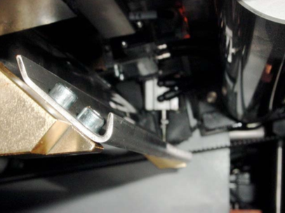
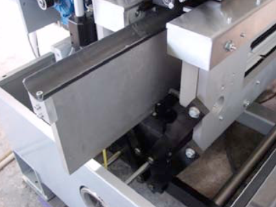
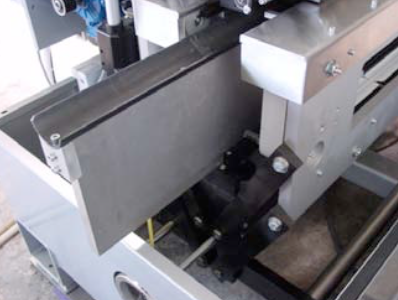
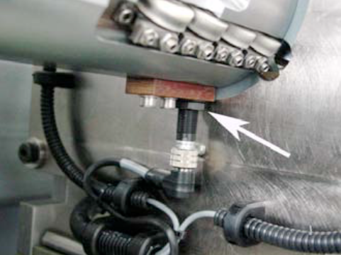
1 or 2 (sender/receiver) sensors are fitted behind the first pair of rollers to recognize double sheets.
Sensor in the lower part.
A pneumatic cylinder operates the ejection flap.
The double sheets detected by the sensor are diverted into this channel by means of a switch point.
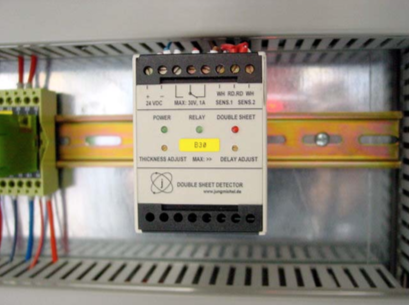
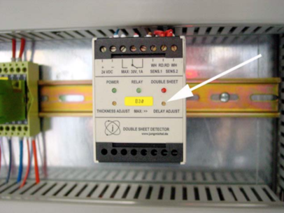
Setting the double sheet sensor
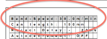
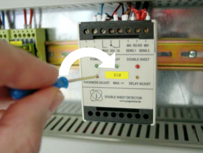
B30
The evaluation unit for the double sheet sensor is located in either the control box (illustration) or in the immediate vicinity of the rollformer, on the feeder side.
To set the sheet thickness, take a single sheet and lay it on the support rails in front of the first roller pair. You can also open the roll- former and lay a sheet into the rear area by hand. Then close the rollformer again.
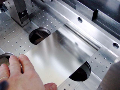
Now turn the single sheet back and forward in the first roller pair by hand with the help of the belt.
The two green LEDs „Power“ and „Relay“ should now be lit up on the evaluation unit.
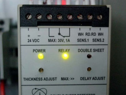
If the red LED „Double sheet“ is lit up, you must carry out a correction.
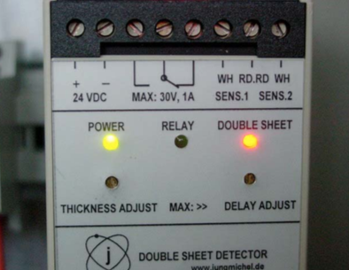
Turn the left-hand screw „Thickness Adjust“ clockwise until the red LED goes out and the green LED „Relay“ lights up. Add 1-2 additional turns in the clockwise direction.
Now carry out the same procedure with two sheets (double sheet).
The red LED „Double sheet“ should now be lit up.
The cylinder should now also be activated. It will be reset again when the sheets are removed.
Do not turn the right-hand screw „Delay adjust“; this is used for the delay of the cylinder stroke.
NOTE:
You will find further details in Book 5 OEM manuals on the CD.
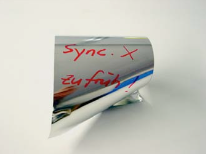
Possible cause:
This is a sample, where the synchronsation is too early. The blank hit the finger/dog of the body transport.
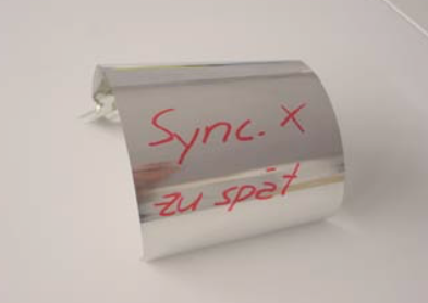
Here the synchronsation is too late. The blank came in alright, but the finger/dog came too early to do the start the transport.
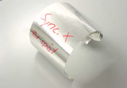
Here a different angle of the damaged blank (late synchronisation).
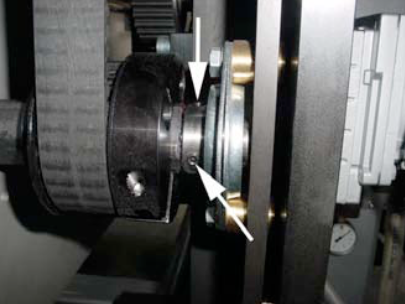
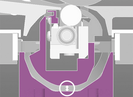
How is the distance between the clutchring and the switch?
Trigger the clutch by hand and check if the red LED light comes on.
This is the LED, which should light up.
Try if you can hold the polygon shaft by hand tightly and trigger the clutch and therefore an immediate machine stop.

If you need to alter the torque of the clutch, do the following:
Loose both black screws of the guiding channel.
Pull the channel to the back of the machine.
Now you can see the clutch.
The basic setting should be 70 NM – see the red mark.
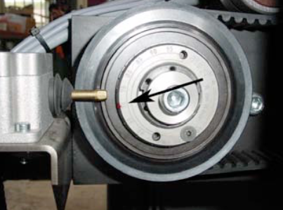
Loose the countersunk screw and take the screw out.
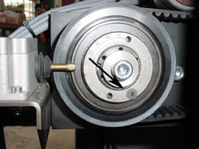
Turn the clutch clockwise with a special tool or a drift punch and a plastic hammer.
You can reduce or increase the torque by steps off 5 Nm, in order to fit the countersunk screw in.
(Picture shows a reduction to 50 Nm)
Now push back the channel back into the machine and tighten the black screws.
For further information find the Mayr clutch manual here:
Copper wire change from 1.38 to 1.24:
Please check following points on your CM16 welder:
Operating Manual CM16 Maintenance Book
Possible cause:
Corretive:
Replace the belt dogs:
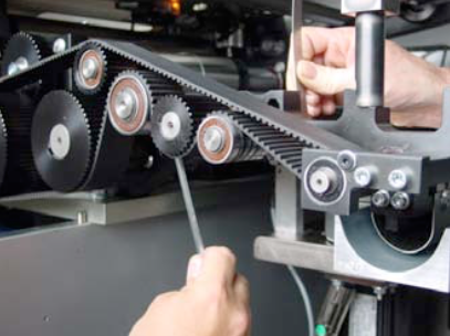
Turn the polygon shaft until the belt dog is easy accessable from side of the machine.
Loose the two screws on each belt dog.
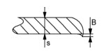
Then replace the belt dogs, be careful that belt dog, is correctly placed in the timing belt, as shown in the picture.
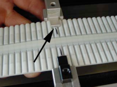
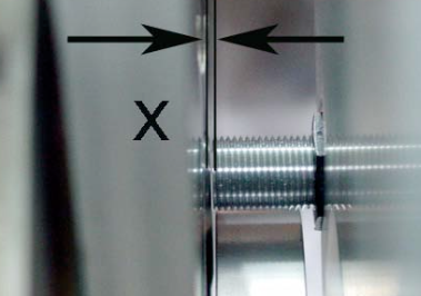
NOTE:
If you need to place the belt dogs, in a new location, due to a damaged belt area, make sure that the distance x is always the same around the entire belt loop.
Also make sure that inside and outside belt dogs are corresponding to each other!
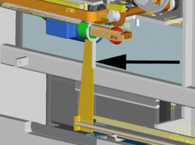
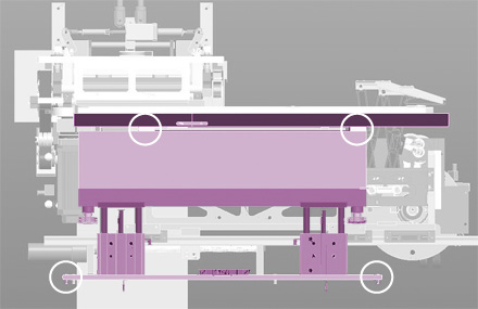
Exchange the body transport belt
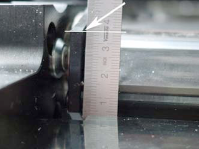
Turn the polygon shaft until a belt dog is inline with reference 3.
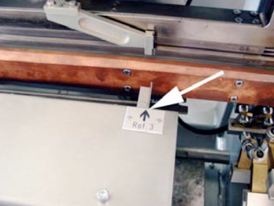
Take off the bracket (see picture),in the back of the front plate.
Then mount the screw loosely to side plate of the synchrostar unit.
Slide the slot of the bracket around the crank handle and tighten the screw.
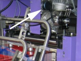
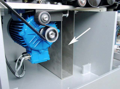
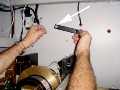
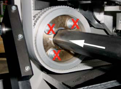
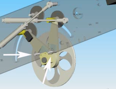
Now you have to release the tension of the synchrostar belt, by loosing the M12 screw.
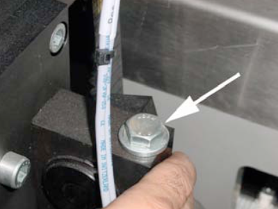
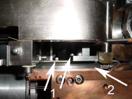
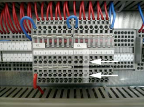
Then release the tension of the body transport belts. The white arrow shows you where you can release the tension of the outside belt. The inner belt has the same feature.
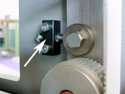
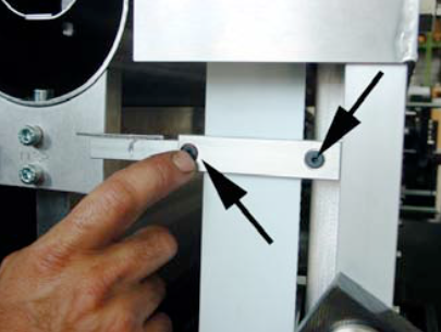
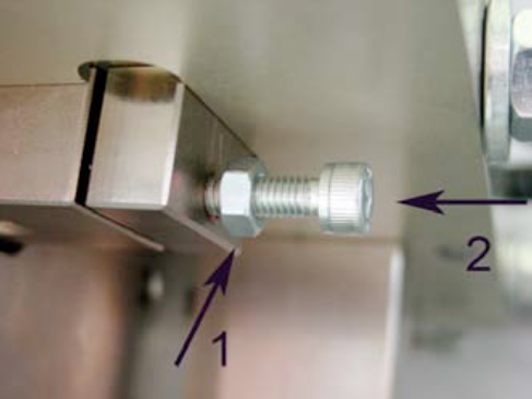
Untighten the two set screws.

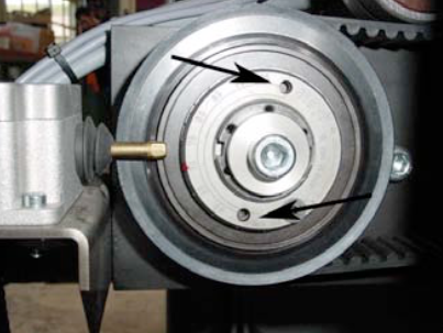
Loose sligthly the three M8 screws (1) first, then undo the M8 screw sligthly too (2). Now you can release the clamping force by turning the M8 nut (3) a little bit.
Now, you should be able to move shaft to the front of the machine and to replace both body transport belts.
NOTE:
Do not loose any other screws, as for example the red marked ones in the picture.
After you have replaced the body transport belts, follow the above instruction in the reverse sequence.
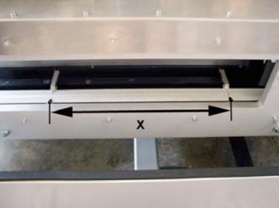
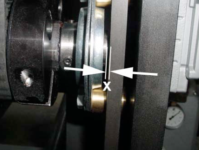
NOTE:
When you push back the polygon shaft and clamp it, make sure that you keep a clearance of x=1mm as shown in the picture.
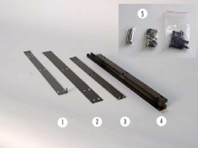
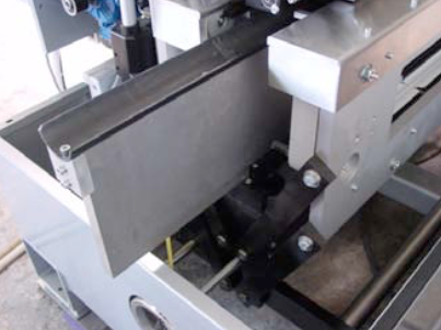
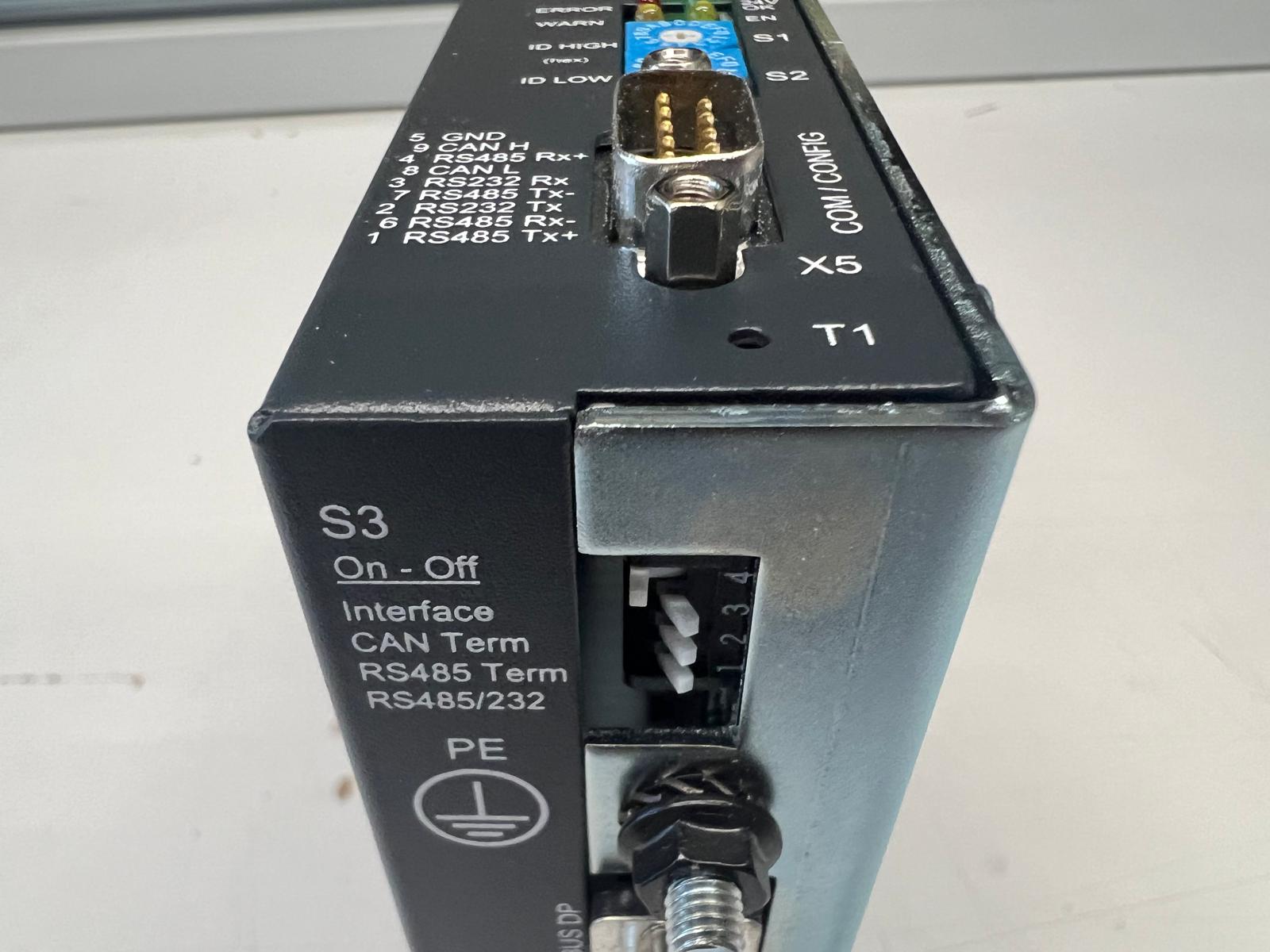
Scope of delivery:
1 – Insulation (over Z-bar) 2 – Insulation
3 – Cover insulation
4 – Z-bar
5 – Set of screws
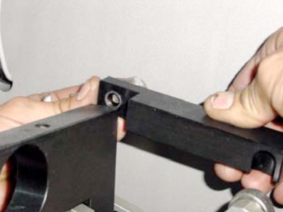
Remove the guiding channel to side of the machine. Then remove the wire from the welding rolls and unlock the tooling plate and slide it to the front.
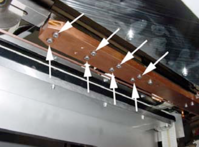
Remove the 8 screws (see arrows) from the welding arm.
Be aware that the screws at the inside are shorter than those at the outside. Do not loose the two o-rings in between.
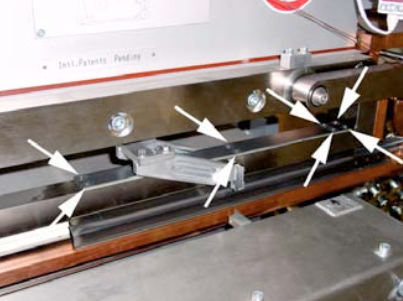
Then undo the eight screws from the cover insulation. Get somebody to assist you to hold to welding arm (heavy).
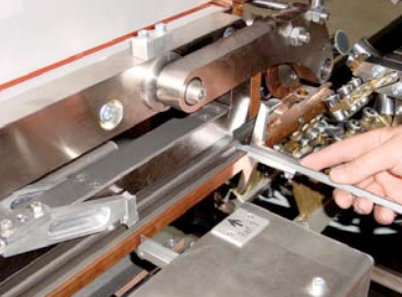
Remove the Z-bar from the welding arm and clean the welding arm with a dry rag.
NOTE:
When you mount the new Z-bar with the insulation, make sure you put some grease on the surface of both insulations and align the Z-bar centered with the depth gauge to the welding arm.

IMPORTANT:
Put also some grease all around these insulated screws.
When you mount the welding arm, do also align the arm properly with the depth gauge to the window.
IMPORTANT:
When you mount the welding arm to machine, make sure you are using the shorter screws for the inside! Otherwise the ceramic guiding might get damaged. Do not forget the two o-rings!
We hope your replacement work was successful. Thank for your support!
Cause:
Corrective:
Possible cause:
NOTE: Only applicable for CMX8 with serial number until No.182 (with Linmot controller type E 1130 and E 2030)
Possible cause:
Possible Cause:
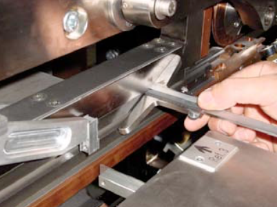
The position of the infeed arm might have shifted, due to a crash or loose screws!
double check the correct position.
Therefore insert „0“ to the can height setting and press „GO“.
NOTE:
If you ever changed the overtravel setting in the tuning level, set this value to „1“.
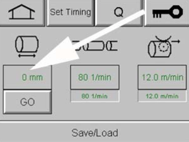
Now measure the distance from the infeed arm to center of the welding roll.
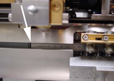
The correct reading should be: 216 mm!
NOTE:
With this reading the canbody will have 1 mm overtravel.
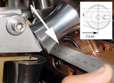
Find the correct position by undoing the four fixing screws of the infeed arm!
NOTE:
This adjustment described above, is only applicable for the old type of CMX8, since the new version has a slot to prevent this issue.
Possible Causes & Resolutions:
Checklist:
Possible cause:
NOTE: all timing settings are stored on the PLC and not on the memory card.
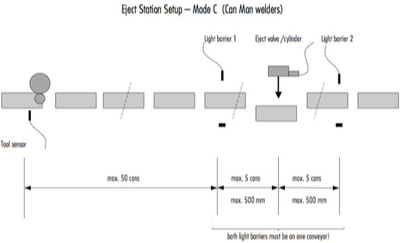
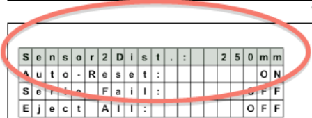
Possible Cause (CM16 / S, X8):
Adjustment of the light barrier distance to eject cylinder might be wrong.
Wrong adjustment of the transport belt speed.
NOTE:
The ejected can should whether touch the can before nor the following.
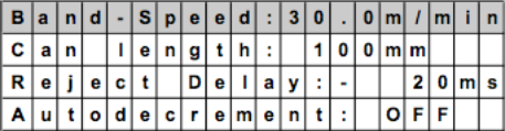
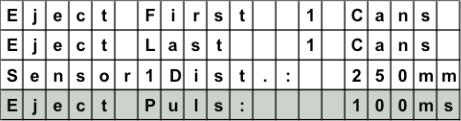
Eject pulse cylinder has to fit to production speed:
Recommendation: 150-200msfor<100cpm 100-150msfor100-200cpm
80-100msfor200-400cpm
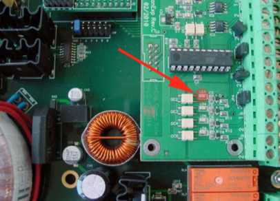
Place a canbody between the second light barrier and check the LED „LD3“ on the eject print (inside the Pacemaker).
Must be „ON“.
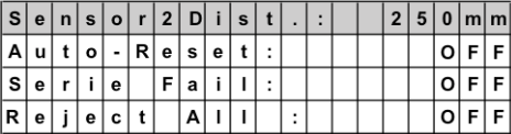
The autoreset needs to be “OFF”. Therefore the can memory will not be reset automatically.
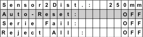
Check, if your hardware parameters are set correctly, according to one of the three layouts.
=> See layouts below!
Possible Cause (Pacemaker):
Read also this checklist here.
Possible cause:
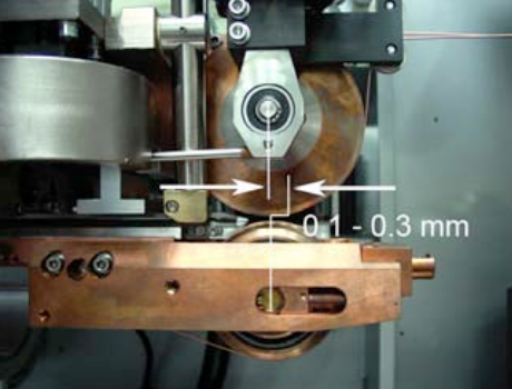
NOTE: Only applicable for the model X8-350!
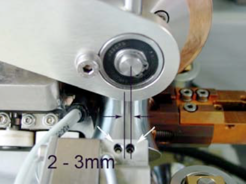
The center of the calibration crown (tooling) should be
X = 2 – 3 mm
behind the center of the pendulum roller head.
he screw with the lock nut has a red seal and must not be changed. This is used to fix the position on the longitudinal axis of the tool carrier with regard to the welding centre.
NOTE:
If you have to change the setting of the calibration crown, you have to loose the lock nut and adjust with the M10 screw accordingly.
In it’s uppermost position, the sucker should lie slightly above the sheet inlet, between the first pair of rollers.
If the setting has to be changed, the screw on the setting ring will have to be loosened.
NOTE:
Further information regarding the exchange of sucker unit of the feeder can be found in Chapter 6. Changeover.
To perform a good timing, the best way is to disconnect the air hose of the cylinder and block it. In that way you can manually lift the sucker unit and find the correct timing.
If you move down the sucker unit to the blank, the vacuum will be activated. Then move up the unit together with the blank until the vacuum breaks.
The correct timing of “breaking” the vacuum is, when the blank just arrives between the roller pair.
In contrast to other machines, the roller head offset is fixed in machines of the
X- series and is therefore not adjustable.
If you have, due to whatever reason to adjust this setting, first make sure what the result of the offset is.
To adjust this offset, you have to loose the two M8 screws of the holder from the welding pressure cylinder.
Additionally you have to loose four M6 screws (1- two are shown), which are fixing the plate (2). Now you can shift the position of pendulum roller slightly in the various hole play.
NOTE:
Do not make any adjustments on this shaft!
Double-check the offset value again and tighten all screws securely.
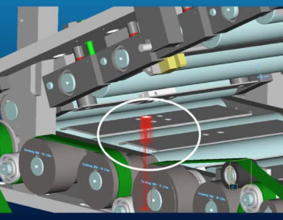
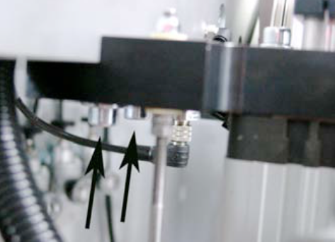
The sensors B1 and B2, which are mounted to main machine plate, need to be readjusted.
Here you have another viewpoint of the two sensors.
The reason, why the wire is still running is, that a distance “x” in the picture is too big. Therefore reduce the clearance for both sensors B1 and B2 too a minimum of 0.1mm.
This might be possible, because the triggering is inverse (this means with a minimal distance to the sensor, it results a max. frequency.
NOTE:
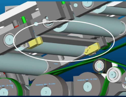
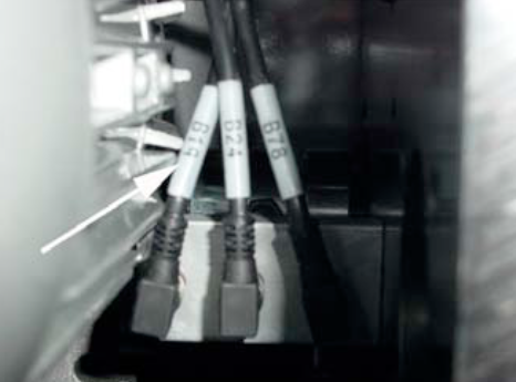
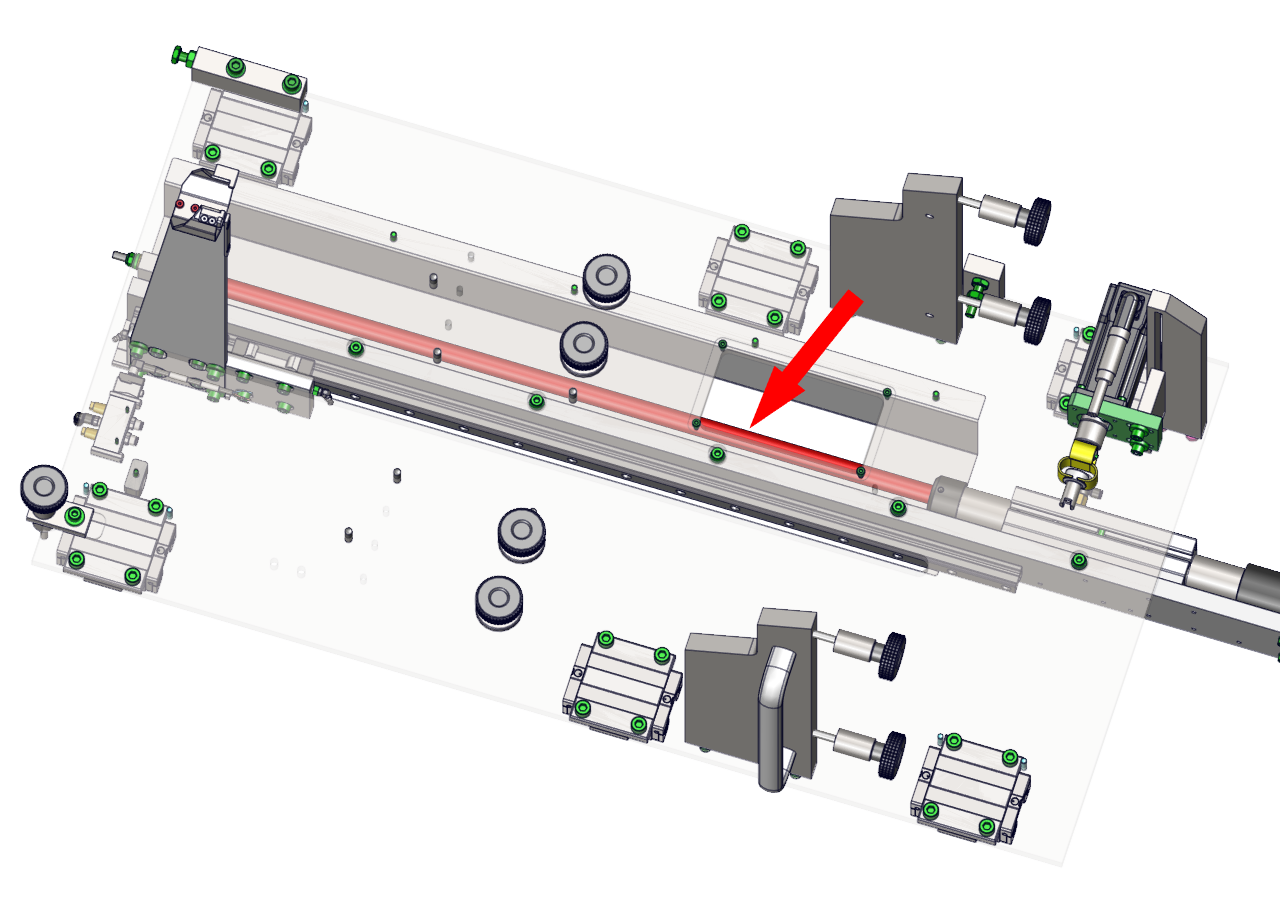
The positions of the screws for the sensors B19, B24 and B78 have been set in the factory, and should not be adjusted. If something has changed nevertheless, you should follow the detailed description below.
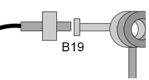
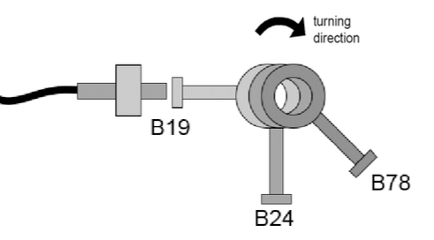
B19
Three sensors are located on the right near the feeder drive M8.
Sensor B19 (left) controls the vacuum valve of the suction beam.
After „breaking“ the vacuum, the position of the screwhead for the sensor B19 must be active. Therefore the position should be chosen between „breaking“ the vacuum and the lowest position of the sucker unit while traveling down.
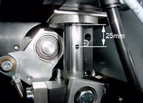
B19
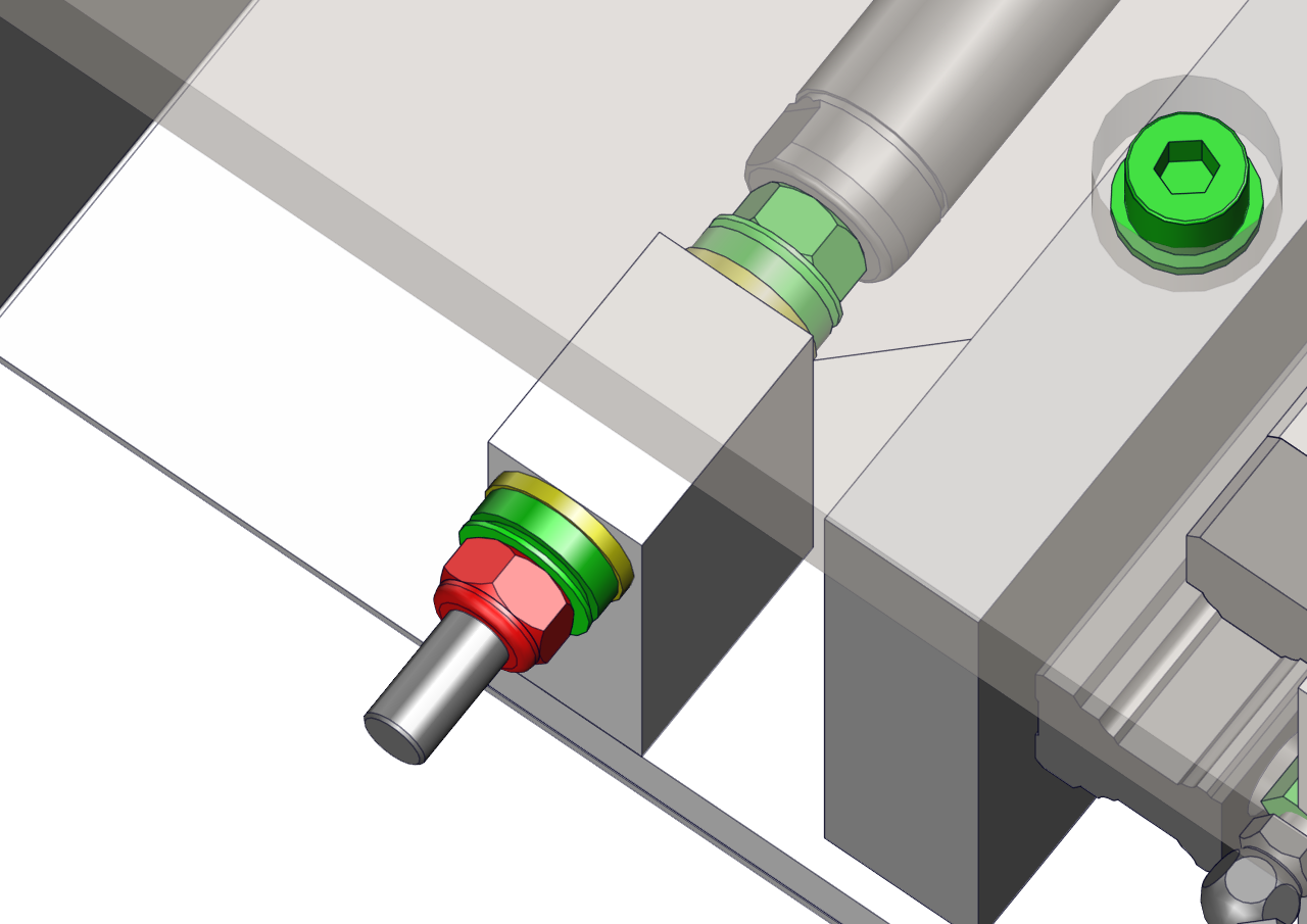
The correct setting for B19 – active, should give you distance of approx. 25mm from center of the hole to the block.
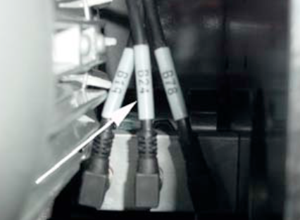
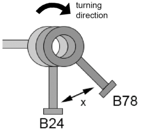
B24
A hexagonal screwhead activates the sensor B24 (center), which then opens the channel flap.
NOTE:
The opening time of the channel flap, can be
extended through software (see Chapter 4.5.2. in Book 1)
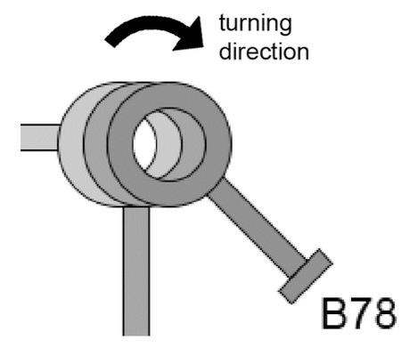
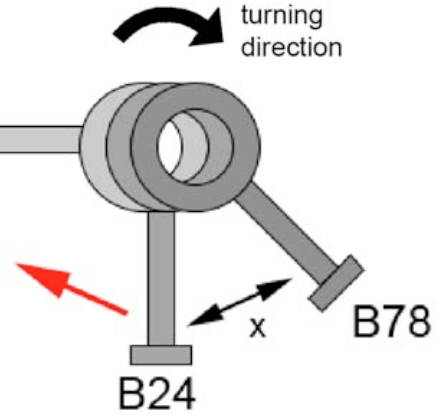
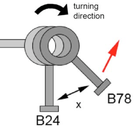
B78
A hexagonal screw activates the sensor B78 (right), which provides the timing for the feeder (synchronization)!
NOTE:
This signal comes from the PLC in the elevating platform version, so no B78 is used in such an application.
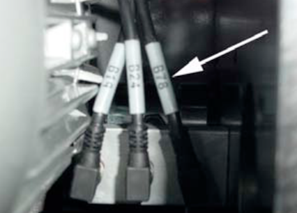
The „active“position of the screwhead for the sensor B78, can vary depending on the rollforming speed.
B24 B78
The signal of B78, always follows the signal of B24, that means that the flap must be closed (B24), before the body pusher starts (B78). The distance, resp. the angle between the two screwheads is fix (at approx. 25 – 45°).
B19 B24 B78
The correlation of the three screwheads. View from toward the electrical cabinet. This setting is based on:
Can diameter 66 – 99mm
120 cans/min
Rollformer speed of 190m/min (49.5Hz)
With a higher rollforming speed, or if the blanc feeding is too late, or you get a damaged blank beginning, you have to move both screwheads slightly clockwise.
With a lower the speed of the rollformer and jams the blanks from the backtravelling body pusher, you have to move anticlockwise.
NOTE:
Make sure that the “activator” screws are tightened and locked and not touching the sensors.
NOTE:
A wrong setting of one of the sensors (B19/B24/B79) will not show a direct related error message.
An incorrect setting of B19 will cause destacking problems and the incorrect setting of B24 & B79 will cause synchronization problems.
Possible cause:
Possible cause:
This can only happen on higher can heights. The canbody to be welded, is extending with its back into the rollforming area, while the next tin plate is coming out of rollformer and touches the backside of the tin plate. The sharp edge of the rollforming plate scratches paint away. This paint is being welded thereafter in the seam.
Correction:
Corretive:
WARNING: Do not adjust pressure switch unless synchronized / confirmed with / from Can Man!

Corretive:
Problem:
Error message: “Jam canbody transport”
Possible Causes & Resolutions:
Additionally checkpoints for X8 with air cylinder downstacker
NOTE: If you did remove the bracing, reassemble correctly. Check the insulation and tighten the self-locking nut only slightly, that the connection can adjust itself.
Report all steps, new or different settings, and old and new production parameters (can size, cpm, weld speed, weld current, weld frequency, current wave-form and transformer step) for an easier overview and follow-up ! (www.canman.ch /Open new ticket and add your document)
Note on which tin-plate parameters (thickness, hardness, tin coating inside / outside, rolling direction, BA or CA, supplier, printed or not) such faults occur, and on which tin-plates not !
Basic parameters & settings to be checked first
Checklist to Avoid Micro Leaks
Micro leaks can occur within the seam and beside the seam – especially on cold-formed areas like necking, beading, flanging or seaming -, even if all above mentioned basic parameters & settings seems to be correct.
Micro leaks can have various sources: Wrong settings on the welder, tin-plate parameters which support such faults, worn or wrong machineries in the downline, or tin-plate parameters which do not fit to beader, necker, flanger and seamer.
For a better visual understanding put the faulty-can bodies in a water bath, and inspect the leaking area by a microscope. Store the pictures if possible!
Checklist to Avoid Flange-Cracks
Flange cracks can occur at the beginning and the end of the seam, even if all above mentioned basic parameters & settings seems to be correct.
Flange cracks can have various sources: Wrong settings on the welder, tin-plate parameters – for instant parallel rolling direction – which support such faults, worn or wrong flanger in the downline, or tin-plate parameters which do not fit to the flanger and or seamer.
For a better visual understanding put the faulty-can bodies in a water bath, and inspect the leaking area by a microscope. Store the pictures if possible!
Download PDF here
Possible cause:
Special settings:
Download PDF here
Download PDF here
Possible cause:
The damaged/bended corner is touching first the inner catch rail.
The inner catch rail looks like a hook and will be found underneath the lower rollformer shaft on the catch station.
By changing the horizontal level of the catch channel slightly, the roll-forming direction of the tin plate will be changed/affected, and the whole tin plate edge should touch the catch rail equally.
We recommend following maintenance procedures:
Order numbers:
Safety data sheets see below:
The error occures when there is a problem with the measurement of the wire speed (not wire speed by self).
If there is still a problem with the measurement of wire speed, you can proceed as follows to restart production:
Please note: The workaround described above is not recommended for permanent production!
P03 = positioning countering error
Possible causes:
Maintenance, cleaning and insulation check (can be used in general for any welder)
Procedure:
Tubes have to be insulated in the area of rollformer, to avoid any contact to the ground.
(In the area of the lower welding arm is a simple insulation not possible).
− Take off the grounding cable from the lower copper plate going to the welding transformer
(Do not forget to place back after you finish).
− Clean the whole secondary circuit as good as possible by rag and compressed air.
Blow from rollformer side towards overhead exit conveyor, to protect the bearings in the rollformer.
− Mount the Z-bar back into the arm and measure the insulation by Ohm-meter > 10 Mega Ohm!
insulation plates).
− Check also every bearing. Attention: Most of them have ceramic balls, marked by a red point!
Make sure you are using only stainless steel screws and washers and lubricate the threads again!
Possible cause /checklist:
Possible cause:
Possible cause/checklist:
The recipe helps to adapt the speed of the incoming can into welding roller and the actual welding speed. In the best case, those speeds are equal.
Below you find a table of this recipe in steps of 10 mm can height.

Turn the wheel of the synchrostar, that the pusher finger is as close as possible to the welding roll.
Measure now the distance from the top of the pusher finger to the center of the welding roll.
Distance = Can height – Overtravel Example:
Canheight: 122mm Overtravel: 4.8 mm
Distance: 117.2 mm
Possible cause:
This problem occurs, if the main switch of machine is turned on, but the machine is not running production for a longer period. The cooling plate of servo drive is heating up, because the water valve is turned off during this time, to prevent condensation water.
Turn off the main switch, if you don’t run the machine for a longer time.
To get rid off the error with overtemp. servo drives you can go to the „Tuning page“. Press the button to switch on the main valve for the cooling system manually. Keep this button pressed for a few minutes, the system will cool down and you can start the machine normally. If you close the “Tuning page”, the main valve is switching back to automatic mode, controlled by „Production ON/OFF“.
Possible cause:
Possible cause:
Possible cause:
Possible cause:
Possible cause:
Possible causes:
How to reset:
The recipe helps to adapt the speed of the incoming can into welding roller and the actual welding speed. In the best case, those speeds are equal.
Below you find a table of this recipe in steps of 10 mm in can height.
Turn the wheel of the synchrostar, so that the pusher finger is as close to the welding roll as possible .
Now measure the distance from the top of the pusher finger to the center of the welding roll.
Distance = Can height – Overtravel
Example:
Can-height: 122 mm, Over-travel: 4.8 mm
Distance: 117.2 mm
The position of the welding roll (WR) has an influence on the overlap at the beginning and at the end.
| WR slightly too high | = Overlap at the beginning less |
| WR slightly too low | = Overlap at the beginning constant |
| WR higher | = Overlap at the end better |
| WR lower | = Overlap at the end less |
| WR lower | = Overlap at the beginning less |
If you still couldn’t resolve the problem, read more at: I have problems to keep a constant overlap
Air Maintenance Unit
Oil:
Aral Vitam XR 46
(Festo – Part No. 12009388 T116)
Vacuum Pump
Mineral Vacuum Pump Oil
Multi Lube 100 – 750212 (Rietschle)
CM Article No. 003634 (5-lt container)
Cooling Unit
Coolant lubricant Zubora 92 F (standard)
CM Article No. 002609 (20-lt container)
PowerRoll™ Coolant H1 (food grade)
CM Article No. 011494 (7-lt container)
Gearbox
CLP 460 Oil
(e.g. Shell Omala 460)
See also data sheet on CD-Rom in Book 5
Central Lubrication Unit
Lithium Complex KP2P-30/EP – DIN 51502
NLGI Class 2 – Application –30 to +150°C
CM Article No. 007857 standard (400g)
CM Article No. 007858 food grade (400g)
Safety Data Sheet Cooling Lubricant
NOTE:
The safety data sheet of cooling lubricant you will find on CD-Rom in Book 5 in file „Cooling unit“
The center of the calibration crown (tooling) should be X = 2 – 3 mm behind the center of the pendulum roller head.

To adjust the position, tip the „tool out“ symbol. ![]()
Then you have to loosen the two M10 screws on top of the tooling plate.
Then you loosen the M6 counternut (1) below the plate, then you can adjust the position with the M6 screw (2). When you turn clockwise, you will reduce the distance, when you turn counterclockwise you increase the distance between the calibration crown and the pendulum roller head.
Tighten the counternut (1) again and then tip „tool in“ to check the position. ![]()
The correct setting!
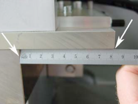
An alternative spot to measure the correct distance is below the tooling plate:
X = 82 – 83 mm.
Remote maintenance:
In the electrical cabinet a modem with a remote maintenance adapter is integrated. Therefore you can do small changes over the phone line.

Recommended is an analog phone line with a direct phone number, with no internal connection through a switch board.

CAUTION:
Disconnect the phone line, if not in service! The remote maintenance system depends on a very good quality phone network. A bad network will make the service impossible.
NOTE:
There are two possibilities to do maintenance work or updates to the PLC Software.
Remote maintenance:
In the electrical cabinet a modem with a remote maintenance adapter is integrated. Therefore you can do small changes over the phone line.
Recommended is an analog phone line with a direct phone number, with no internal connection through a switch board.
CAUTION:
Disconnect the phone line, if not in service! The remote maintenance system depends on a very good quality phone network. A bad network will make the service impossible.
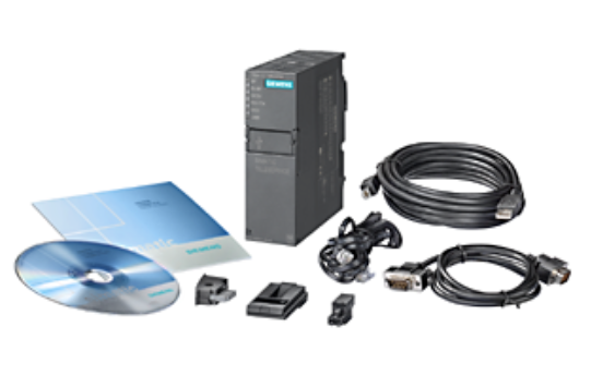
PLC Software Siemens Step 7:
The Siemens PLC is programed by the Siemens PLC Software Step 7TM, the panel (Touchscreen) by WinCC flexibleTM.

The following requirements are necessary to provide this service:
– Notebook with Software Step 7TM and
WinCC flexibleTM from Siemens
– MPI/DP (Profibus) interface
– Technical engineer with the software
knowlegde of Step 7TM + WinCC flexibleTM.
CAUTION:
If you change the software without prior consultation of CAN MAN, the works guarantee becomes void.
Possible causes:
Possible causes:
Possible causes/checklist:
Possible causes:
The instructions below show you how to connect the following signals: a) Line control b) Error powder unit and c) Release powder
Signal: line control
In order to switch off the downline due to an error, the PLC has a prepared input. To use this input, we need a potential-free signal from the downline, which is closed when the line is ready. Use the terminal E5.1 to connect the line control.
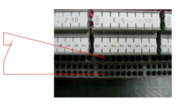
As soon as an error occurs, the destacking of the sheets stops and after an adjustable delay the wire-run and the remaining drives. The canbody transport continues to run slowly. This mode plus the flashing of the key „Production ON“ shows the operator the status of the line stop.
ATTENTION:
Machine begins to produce independently again, respectively after the release of the line control.
This input should be connected the same way as the line control. Here as well we need a potential-free relay contact of the powder unit. But this contact needs to be open, if there is any error. This signal needs to be connected to E126.7.
The production shuts off, if an error occurs. After that the operator needs to switch on the machine.
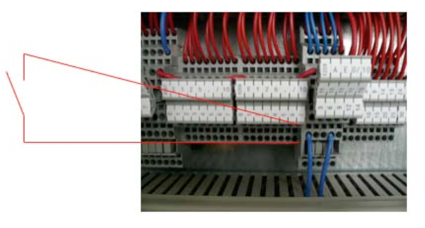
Signal: Release powder
In order to switch on the powder, we provide a change-over contact. The contact switches as soon as the production or a single can is triggered. In order to provide enough time for the initialization of the powder, the destacking is delayed by an adjustable time. Before you connect this signal, you have to remove the comb bridge (1) and the link (2), in order to make the contact potential-free.
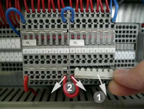
Use the terminal K6.2 (A124.2).
NOTE:
Consult the electrical scheme of your welder to double-check the various input signals. In case you are not successful with the connection, contact a CAN MAN electrician.
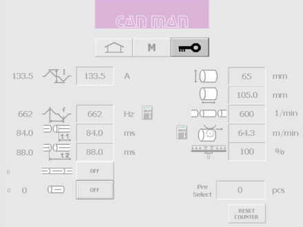
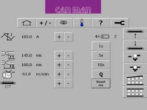
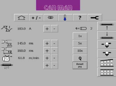
Cause 1:
The setting of t1 and t2 is wrong. If the timing is wrong the PM cannot execute the signal, which is necessary to memorize the canbodies in the reject unit and to start the record of the graph.
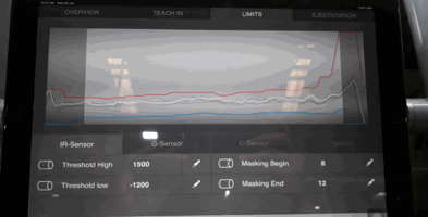
Setting of t1 and t2:
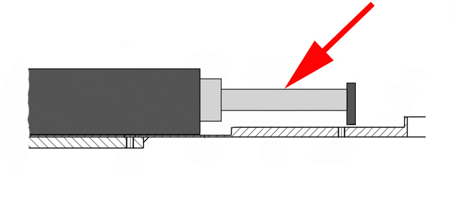
t1 defines the starting point for the reduced current time window. ![]()
t2 is the time, where the reduced current windows ends. t2–t1= thus is the timespan for the reduced current, therefore t2 > t1! ![]()
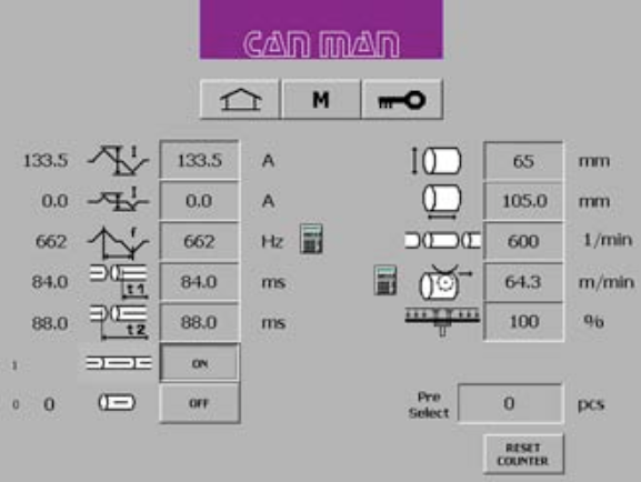
NOTE:
The value of t2 and t1 needs to be smaller as the cycle of one single can.
For example:
A production of 300/min. corresponds to a cycle time of 200 ms/can. Production of 600/min. corresponds to 100ms/can.
NOTE:
For a more detailed explanation of timing t1 and t2, consult your manual book 2, chapter 5.6.5. “Setting of Parameter t1 & t2 for reduced Current and Overlap Check“.
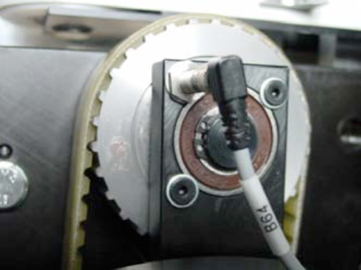
Cause 2:
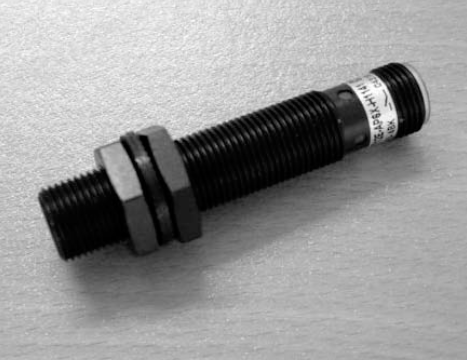
Check the inductive proximity switch B64 at the final pusher unit for function, operating distance and defect.
B64
Final pusher (Synchrostar II): Sensor B64.
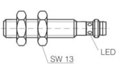
Description:
Inductive proximity sensor for embeddable mounting.
Polarity: PNP
Output: NO. or NC.
Operating distance: 2mm
Cause 3:
Check the tool switch B6 in the calibration tool for function, operating distance and defect.
B6
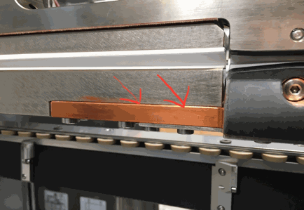
The position of the welding sensor B6, can be almost flush. Just make sure that you do not get scratches on the canbodies.
The height of the sensor can be adjusted here (see arrow).
Inductive Sensor (magnetic field resistant)
Mounting mode: flush
Function principle: inductive/normally open Rated operating distance: 3 mm
Find a complete error list together with the interpretation of the error codes
Download PDF here
Possible causes:
NOTE:
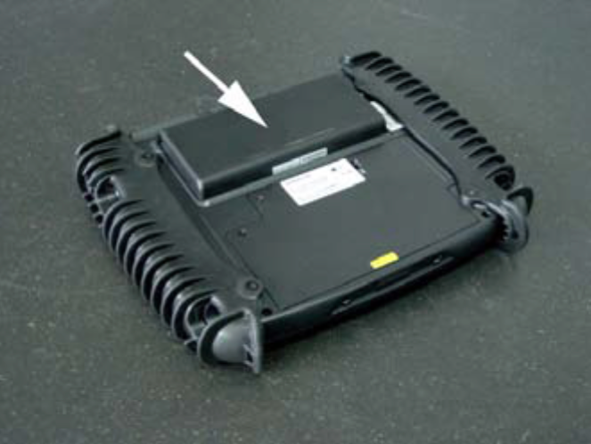
If you do not use the panel for a longer period (several weeks), the device should be turned off on the backside. Otherwise the internal battery will discharge and will get damaged!
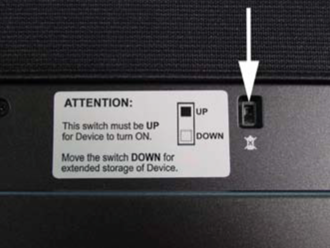
If you push the button on the right side, you are able to see the status of the integrated battery and optional available second battery.
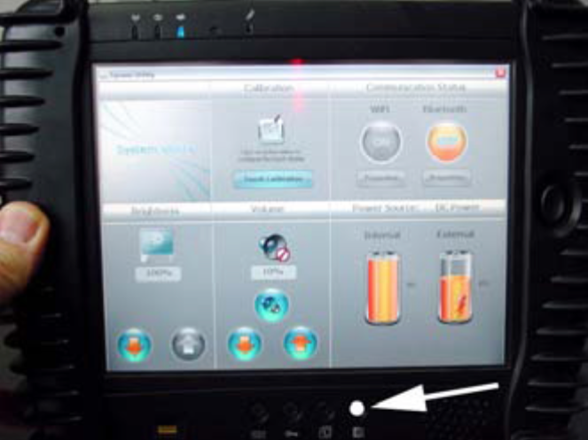
The optional second battery is located at the back of the device.