The motherboard battery is a CR2032 lithium-metal cell. It is used to supply power to the clock integrated on the motherboard. If the battery is depleted or missing, the date and time are displayed incorrectly. Recommendation for replacement interval is 5 years.
For instructions on how to replace the battery use the download link below. You will also find the correct battery type there.
Problem:
The cold plate of the IGBT modules in the pacemaker HF (V1&V2) has reached the maximum temperature limit of 55°C.
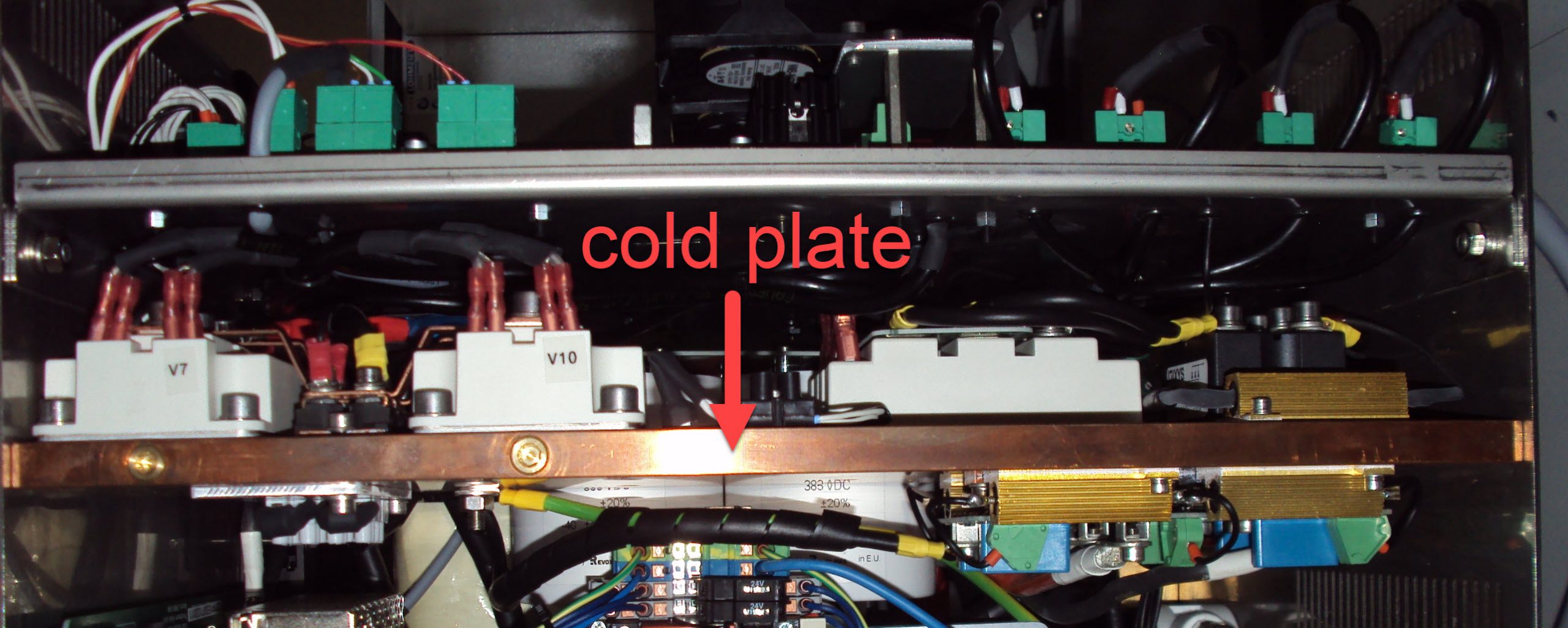
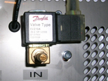
In normal operation, solenoid valve Y126 should open at 35°C and close again when the cold plate has cooled down to 30°C.
Note: If you push the down arrow button, you can observe all values, including the current temperature values.
![]()
Possible Causes & Resolutions:
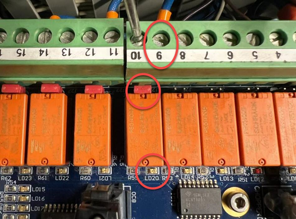
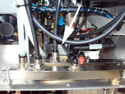
Check following as soon as the solenoid valve Y126 switches on (when cold plate has reached 35°C):
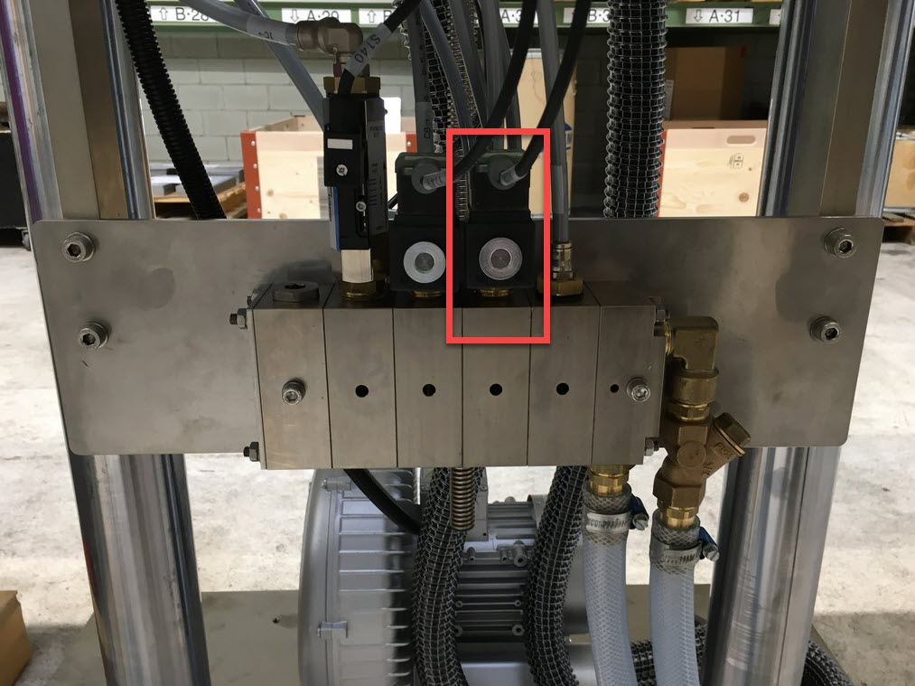
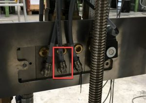
Note: In the Pacemaker HF V1 devices, the solenoid valves are integrated in the Pacemaker HF housing. The system works similar, even the solenoid valve type is the same.
If the solenoid valve Y126 does not switch on, although the temperature exceed 35°C, check the following points:
Error message: Setup data corrupt / User data corrupt
Resolution:
Reason for error message:
Possible causes:

Possible cause:
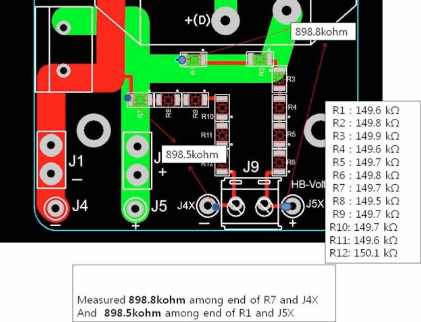
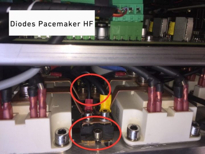
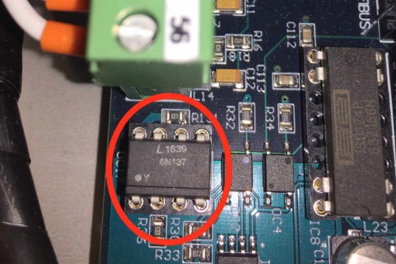
Diodes between IGBT’s are damaged
Measure / exchange diodes:
Scroll down in the display menu until you reach the temperature display. Observe, if after crossing the switching threshold, the temperature doesn’t change, that the solenoid valve is blocked (when the 2nd thresholds are reached the message “over- or undertemperature” will be displayed).
NOTE: The error message “Ths too low (Ths = Temperature Heatsink)” might be an indication for a contaminated valve.
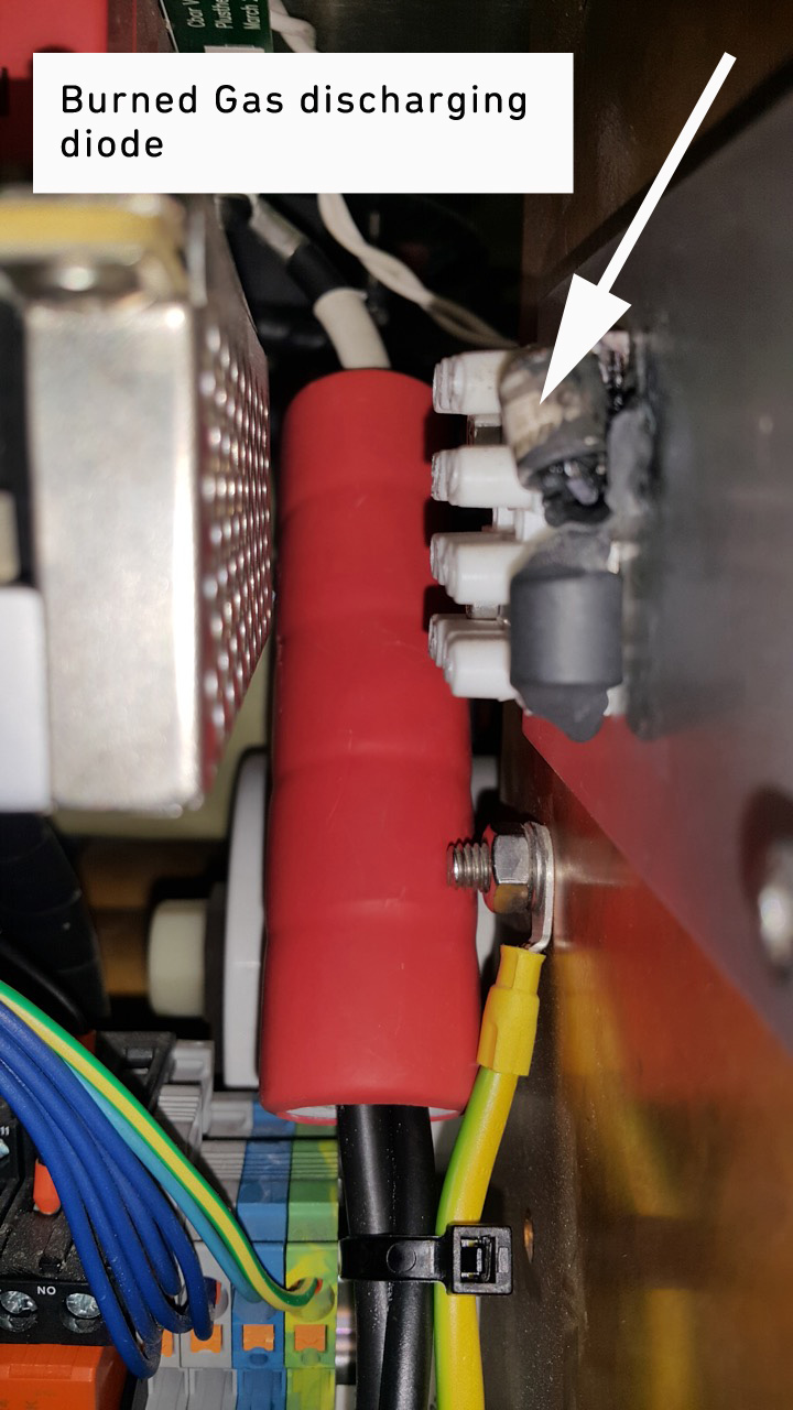
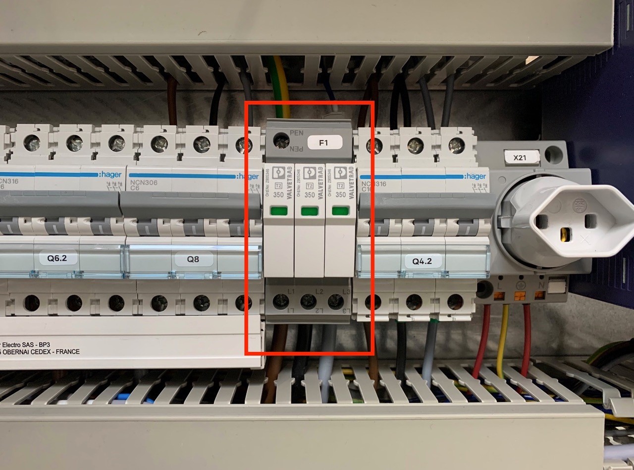
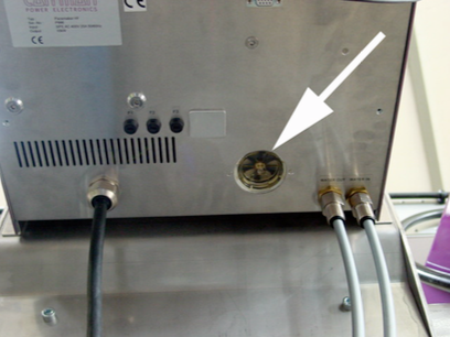
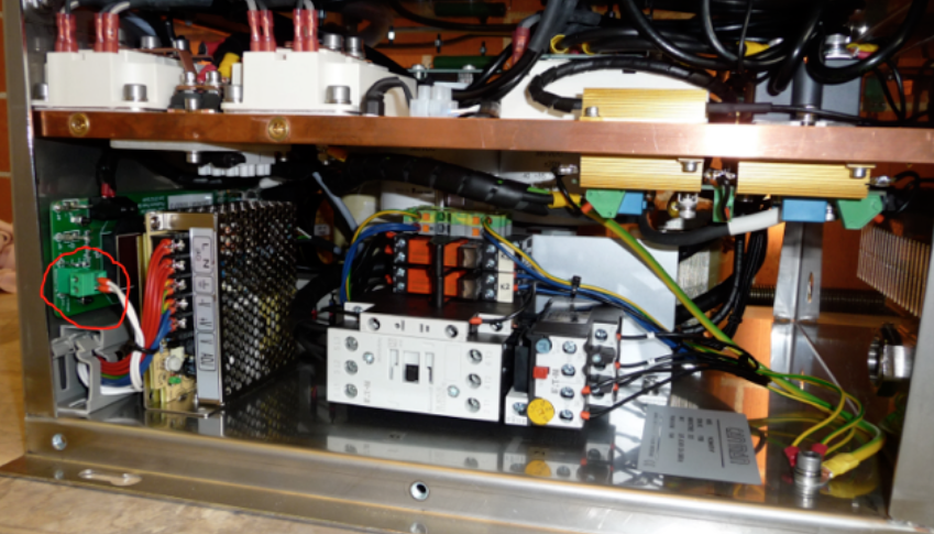
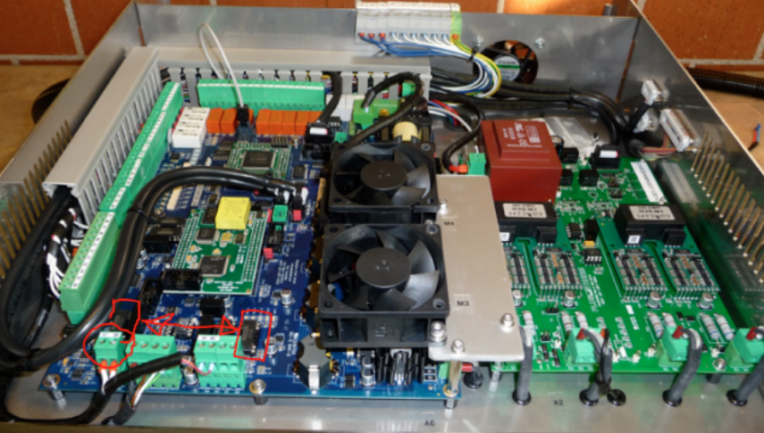
An overvoltage suppressor (or surge suppressor) is an appliance designed to protect electrical devices from voltage spikes. A surge suppressor attempts to regulate the voltage supplied to an electric device by either blocking or by shorting to ground voltages above a safe threshold.
These surge suppressors are built in to the latest Pacemaker models and machine controls (from 2009).
Check, if one or more modules of the surge suppressors are red/defect. Replace the red modules.
Attention!!!
Do not bridge the signalling contacts and run the machine with defective red modules because they no longer protect the system from voltage peaks!!!
If the modules are defective, check the main supply. Measure and check all voltages between the phases and all phases to earth before exchange the modules and restart the machine.
Check
– Check the cooling-water-inlet.
– Check the “Ths” and “Tamb” on the display.
– Check the small fans of the Pacemaker
NOTE:
The error “Ths too low” means temperature heat sink (copperplate) too low. If the copper plate is too cold. It can damage the unit, if some condensation water flows to the electronic power parts.
Check if the valve closes correctly and clean the valve.
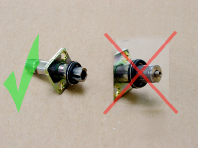
NOTE:
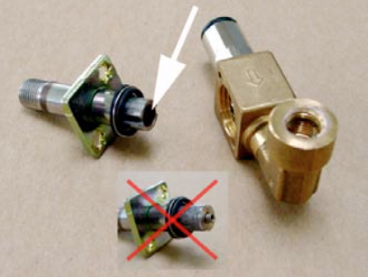
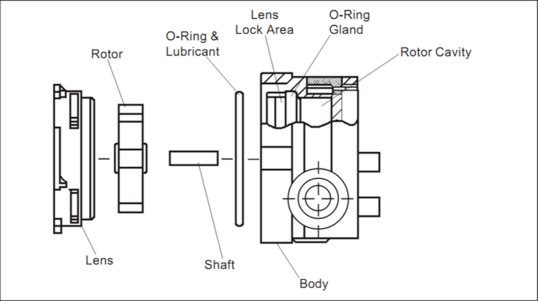
If you reassemble the valve, make sure you do it the right way (see picture)
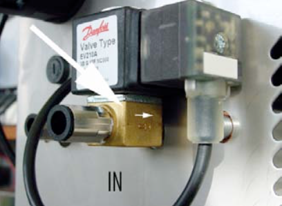
Check the correct water flow direction.
Download PDF here
NOTE: The pictures showing a regular Pacemaker and not a Pacemaker HF as used in the PowerCure, but the issue is the same!
Potential remedy
Possible reason choke coil defective
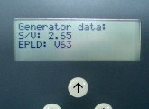
When you start up your PowerCure equipment, the software version (here called generator data) will be displayed during the boot process.
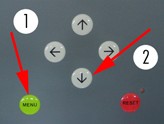
Alternatively the information will we displayed, when press “MENU” and then press the key “down” several times until you get to “Preheater Info”:
There are two Software versions displayed:
e.g. – S/V 2.65 and EPLD V63
Possible cause:
Sparking on the induction coil
HF filter not set correctly (to high)
Check all insulations of the coil and C-bar.
Cause:
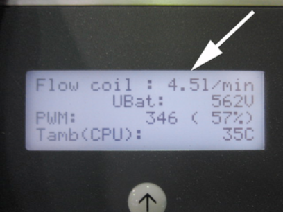
The water flow of the coil is too low!
NOTE:
The standard setting for this error is 3l/min (can be found in the basic setup “rotary minflow”).
The actual water flow is shown in the display. Press down from the main menu on the display until you find the flow coil.
NOTE:
You have to switch “ON” the curing to open the water valve!
Check for possible causes:
Clean the water valves:
Therefore disconnect the water inlet to the Pacemaker HF and blow out the water. Take off the coil and open the valve with a torx screwdriver. Blow out the valve and clean the rubber.
Reassemble the valve properly (insert the closing block with the spring on top, so the rubber is closing the outlet hole.
Clean the rotary flow unit. Follow the instructions below.
If were not successful, replace the rotary flow meter => CM article No 007906
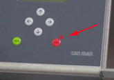
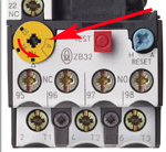
The reset LED flashes and a warning is shown!
If the reset LED flashes, then the system works in a critical state. The unit is still entirely functional, but it should be a hint for the operator to do something against the warning.
Contact Can Man for advice!
Possible cause:
Please check on the white transformer all connections.
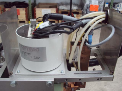
ATTENTION:
Switch OFF the main supply first!
Nuts must be firmly tightened, but do not overtight! Bolts must well fixed in the casting compound.

NOTE:
A loose connection creates an overheating and destroys the transformer and cables!
The IC, which control the analog output, must be replaced. Please request support from Can Man!
Possible cause:
CAUTION – HIGH VOLTAGE:
You are now in the immediate vicinity of parts that produce high electric voltage! There is a danger of an electric shock.
Only performed by “certified electricians”
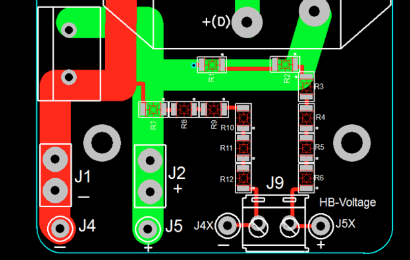
Measure the voltage on the main board clamp 57=”+” 58= “-“ => if the power output is set to 50V it should have about 100mV.
• Check if the Dc-Dc IC has a problem you can exchange it with an other one on the board
(which is unused in your configuration – remove the IC carefully, so the pins are not getting damaged!)