Support

14 Support Entries

Problem:

Everything looks fine but the drives do not start if the green button “Production On” is pressed.

Possible Causes & Resolutions:

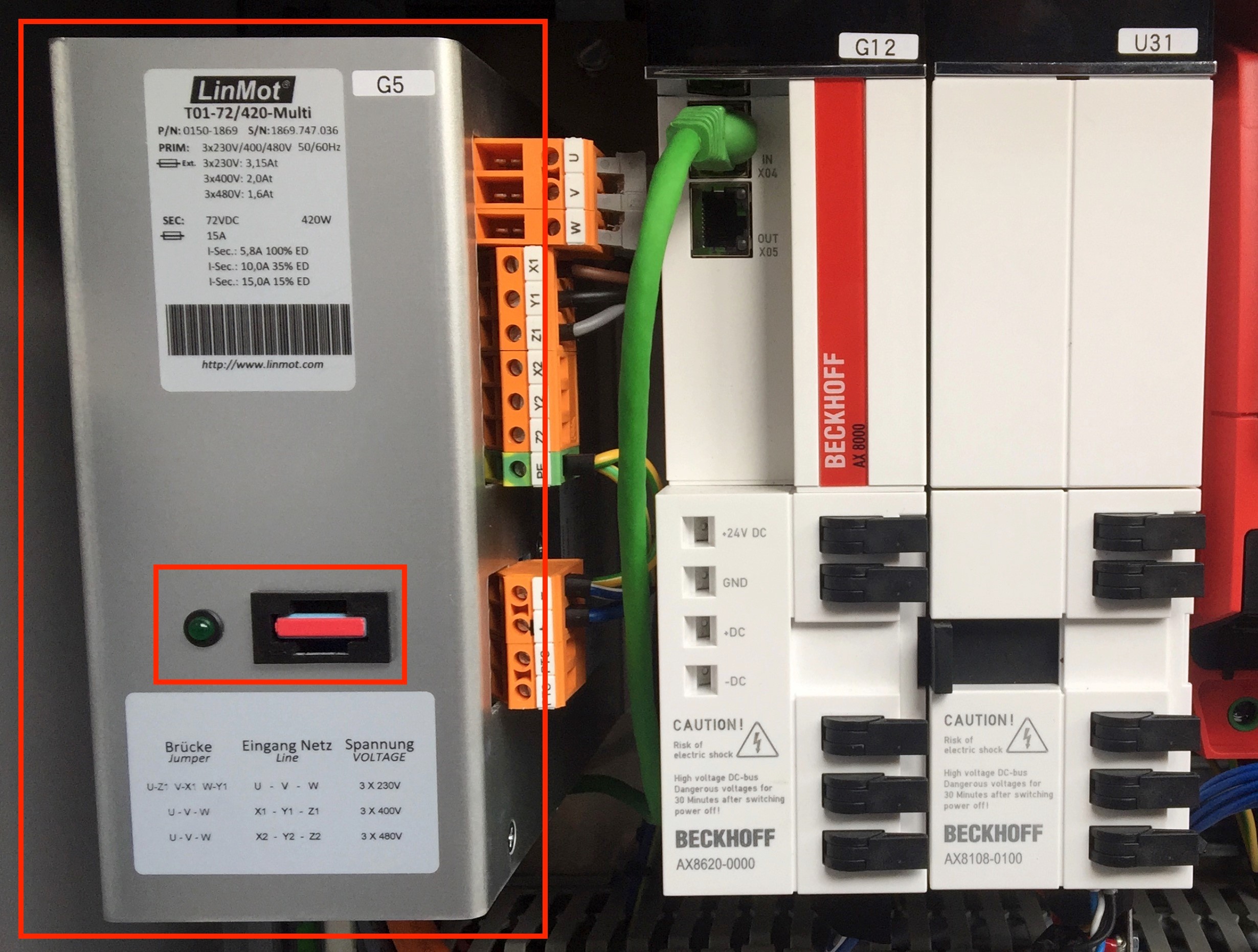
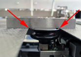
The main power supply 72 VDC of the Linmot controller is missing:

Check the power supply G5 inside the control panel on the second table (see attached picture). Most probably the 15 Amp. fuse is melted. Replace the broken fuse with a new one.
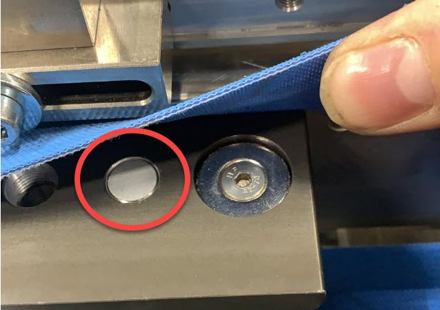
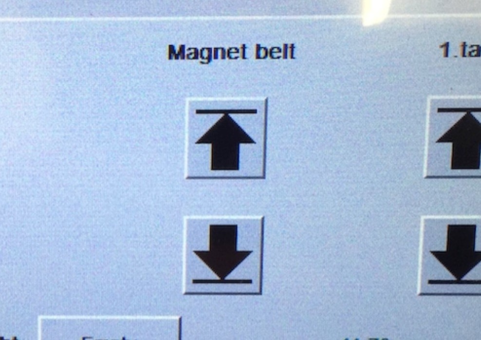
Problem:

Error message „Magnet belt not down” displayed on HMI (magnet belt does only exist on the 2. table on a duplex slitter), and arrow buttons „Up” and „Down” for magnet belt are not visible anymore.

Possible Causes & Resolutions: 

Arrow buttons magnet belt up may be visible for a short time and pushed during start up of panel.
Delete of error message:

  1. Login with canman user => Contact CANMAN for password
  2. Go to Setup
  3. Change the function Single slitter to OFF (See attached picture)
  4. Go back to main screen. Now the up and down button for magnet belt will be visible.
  5. Push and hold the arrow button down for magnet belt until the error message “Magnet belt not down“ disappears.
  6. Go back to the canman settings and set the function “Single slitter” back to ON.


Note the adjustment of the clearance of the roller after the BIG8 monobloc cutting heads is ELEMENTARY to prevent bow cuts!

Check if the roller is not “tilted” (and thus one-sided “in the air”), refer also to manual of your slitter how to adjust the roller.


Possible causes:

  • If your Big 8 slitter does have only one long magnetic rod-sensor, Big 8 cutting heads shall not touch each other, because the magnetic positioning rings (sitting around magnetic rod-sensor and mounted in each Big 8 unit), could interfear each other.
  • The amount of Big 8 units must always be equal with the amount of Big 8 icons shown on the display.
  • Check the squareness of a couple sheets: From corner to opposite corner, as well as opposite corner distance. Compare both measures: The difference should be < 1 mm.
  • Make sure that the lateral position of the sheet stack is correct: Correct the stack position by the handle, until the sheet does < 2 mm lateral movement till the final position before 1. cutting operation.
  • Measure the sheet flow height on the first table: 0.5 mm below cutting level.
  • Stop 1 sheet before the 1. operation – with centering rollers closed – and check the pressure on the spring roller: Too much load on the spring can damage the sheet.
  • The speed of the first cutters (measure on the carbide knife) must be a around 1 m/min less compared to the speed of the driven conveyor belt.
  • Make sure that both trim-guides (after 1. operation) do have a space of 0.5 mm to the stripe edge!
  • Measure the burrs of all stripes, if necessary grind the knifes!
  • Make sure that one pair of knifes is mounted reversely (helps to guide trim downwards, helps to avoid bow cut).
  • Measure the concentricity of all transport rings, exchange damaged transport rings!
  • Fill-up too big space(s) between the cutters with white guide-rings ! This helps especially for thin sheets and for higher developments. Measure the gap between each guide-rings with feeler-gauge 0.50 mm.
  • Regulate the position of the centering system by the hand wheel, till both trims measure the correct width.
  • Check the parallelism of each trim: Bend the trim, and compare both widths. The result is related to the squarness of the sheets. If the trims are not parallel, it is needed to adjust the alignment of one none-spring tensioned support bearing on the centering device.
  • Measure parallelism of all stripes after 1. operation: Target < 0.05 mm!
  • Set the sensors between both overhead conveyors (after 1. operation) correctly: Laterally, the stripes should not move more than 2 mm after being centered by the 2. centering device!
  • Measure the stripe flow height on the second table: 0.5 mm below cutting level!
  • Measure the blank flow height after the 2. operation: 1 – 2 mm below cutting level!
  • Make sure that enough magnets are mounted in the area before the 2. operation, and that the magnets are mounted at the correct positions. Attention: Too much magnet force will cancel the centering device function!
  • Reset the postion of the Linmot infeed device according to manual.
  • Reset the position of the Linmot centering device according to manual.
  • Position 1 stripe before the 2. operation – with centering rollers closed – and check the pressure on the spring roller: Too much load on the spring can damage the stripe!
  • Check the spring tension of the push finger on the second operation. Maybe it is to low and the push finger does not go back to the right position after moving back to feed the next stripe.
  • Check the mechanical condition of the push finger. Maybe it is worn out and have to much backlash.
  • The acceleration belt for the second operation must be tensioned. Attention!! If spanner is readjusted, the thread bolt can touch the knives. We recommend to chop the thread bolt or take out the spanner and remove the thread bolt! (related for PowerCUT manufactured before 02.2015.)
  • The speed of the Linmot infeed system during transfer into 2. operation must be correct > cannot be measured.
  • The speed of the second cutters (measure on the carbide knife) must be a around 1 m/min less compared with to the speed of the driven conveyor belt (only if lift-table is in use).
  • Measure the burrs of all stripes, if necessary grind the knives!
  • Measure the concentricity of all transport rings, exchange damaged transport rings!
  • Make sure that the grooves of all Big8 z-bars are clean!
  • Fill-up too big space between the cutters with white guide-rings! Measure the gap between each guide-rings with feeler-gauge 0.50 mm.
  • Use the SQM measuring device to measure the angular errors of each stripe!
  • Test the angular tolerances by choosing velocity 1, 2 and 3. Report the differences.

Possible cause:

  • wrong position of a reed sensor
    • check all reed sensors
    • use the help of the display – which shows the status of the sensors
    • consult the timing diagram of the PowerCUT – download here.

Possible causes:

  • the preselect counter is activated but a value is missing
  • the blank collector is full
  • if connected to a line control, it may have triggered a line stop

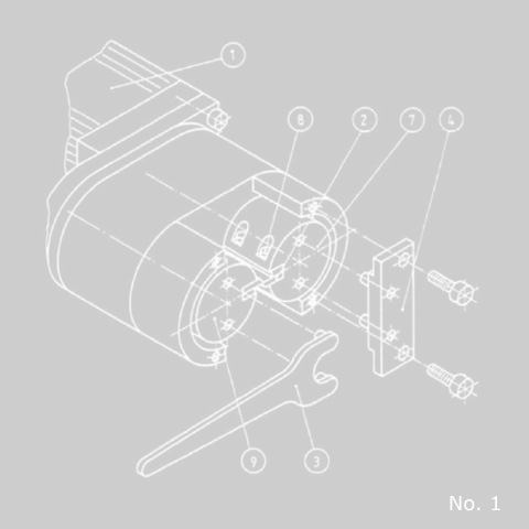
To remove the used cutting blades, two spherical clamp screws M6 (8) have to be loosened. The steps for the fitting of the fixing plate (4), which is part of the standard tools delivered with every slitter, are:

  1. Remove the plastic plate cover, 4 screws M5.
  2. Turn the cutter shaft (7) which is fitted to the drive motor (1) with the special tool (3) until the blade (2) is in the horizontal cutting position.
  3. Secure the direct driven cutter shaft (7) in this position with a fixing plate (4) against twisting. The fitting of the fixing plate (4) is done with 2 M5 screws which were used on the plastic plate cover.
  4. Release the clamp nut (6) of the not driven cutter shaft (9) with the special tool (3) and the point opening socket wrench (5).
    Use the same wrench (5) on the clamp nut (6) beside the drive motor (1). Turn clockwise = to grip
    Turn counterclockwise = to release
  5. Turn the released cutter shaft (9) until the blades are nearly closed together. Place a small piece of 0,02 mm tape between the blades. Turn the cutter shaft (9) until the tape is tied between the blades.
  6. In this position, the clamp nut (6) of the cutter shaft (9) should be tied up with the special tool (3) and the point opening socket wrench (5).
  7. Take away the tape and check that the cutter blades do not touch each other. Turn with the special tool (3), in the correct direction, with the motor driven cutter shaft (7). The ahead running blades should be in this cutter shaft.

Important
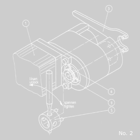
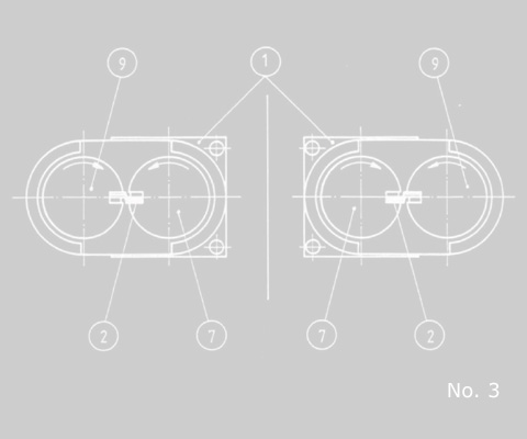
During the assembly of the new cutter blades (2) check that the ahead running blade is on the motor driven cutter shaft (7). See picture no. 3

Nobody should start the unit during the set up. The emergency button should be pressed down, the key-operated switch taken away from the slitter.

Non-compliance of this instruction will cause cutter blade damage or blocking of shafts.

Setting gauge for blank magazine

The setting gauge allows faster adjustment of the blank magazine. This file can be used as a template for individual manufacturing according to specific formats.

Possible causes:

  • wrong cutter setting
  • cutters are blunt
    • grind your cutters
  • watch the sucker unit in front of the 1. cutting operation for too much downwards-bow of the sheet
    • adjust bottom stop
    • replace worn out sucker or parts
    • mount the full range of downholder rings – see picture below!
    • they prevent the bowing movement of the sheets

NOTE: The SQM measuring device can only detect “angular” cutting errors!

Possible causes:

  • Since the slider of the linear motor contains strong magnets, remove dust or small particles from slider with a disposable paper.
  • LED state shown by the yellow LED on the controller or check the hand panel
    • “Sensors / Actors 3/4”
  • Motor resistant according Linmot manual
  • Cable according Linmot manual


Possible causes:

  • make sure that the inner core and the suction cup are on the same level (picture 1).
  • make sure that the suction unit in the upper (active) position is on the sheet metal level (picture 2)


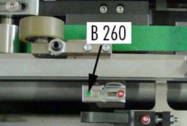
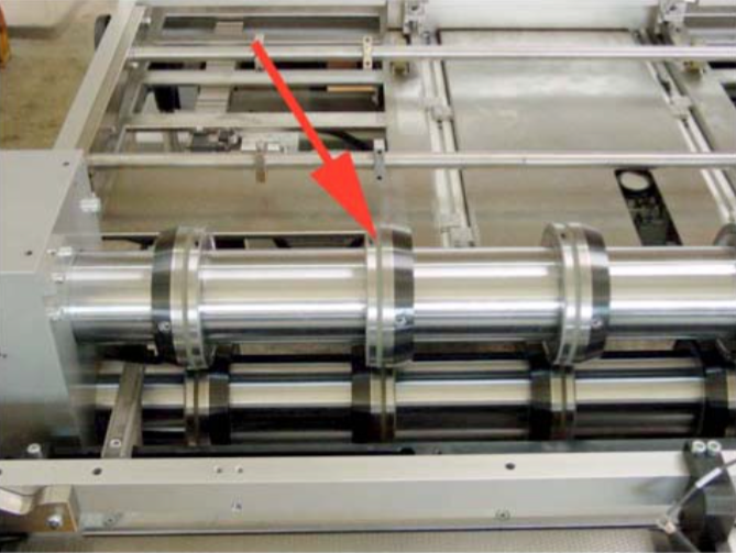
Check function of the reed sensors B256, B257, B258 and B259.

You can find them on the cylinders of the magnetic conveyor (Y125) and transport roll (Y124). Manually activate the two cylinders on the valve block and adjust the reed sensors if necessary.

Refer also to the pneumatic diagram here.

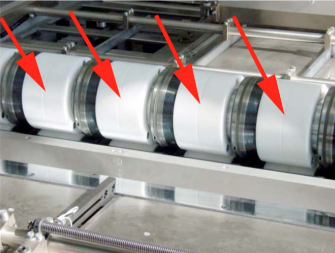
Check the transport rings on the knives: If the rubber is too small (due to heavy wear) conical or much bigger (if no original spares are in use) cutting tolerances can be negatively affected!


Make sure that enough support rings are mounted between the knives. They keep the sheet leveled. The thinner the sheets, the more important it is to keep them flat.


Make sure that all knives are well grinded.

NOTE:
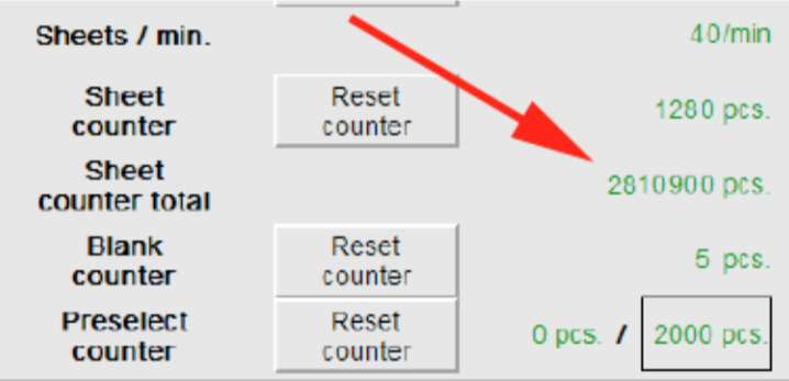
You should regrind your cutters after approx. 3 mio. sheets.


All Can Man content is now also available on the Soudronic Group website.
Where do you want to continue your journey?
All Can Man content is now also available on the Soudronic Group website.
Where do you want to continue your journey?