Problem:
Everything looks fine but the drives do not start if the green button “Production On” is pressed.
Possible Causes & Resolutions:
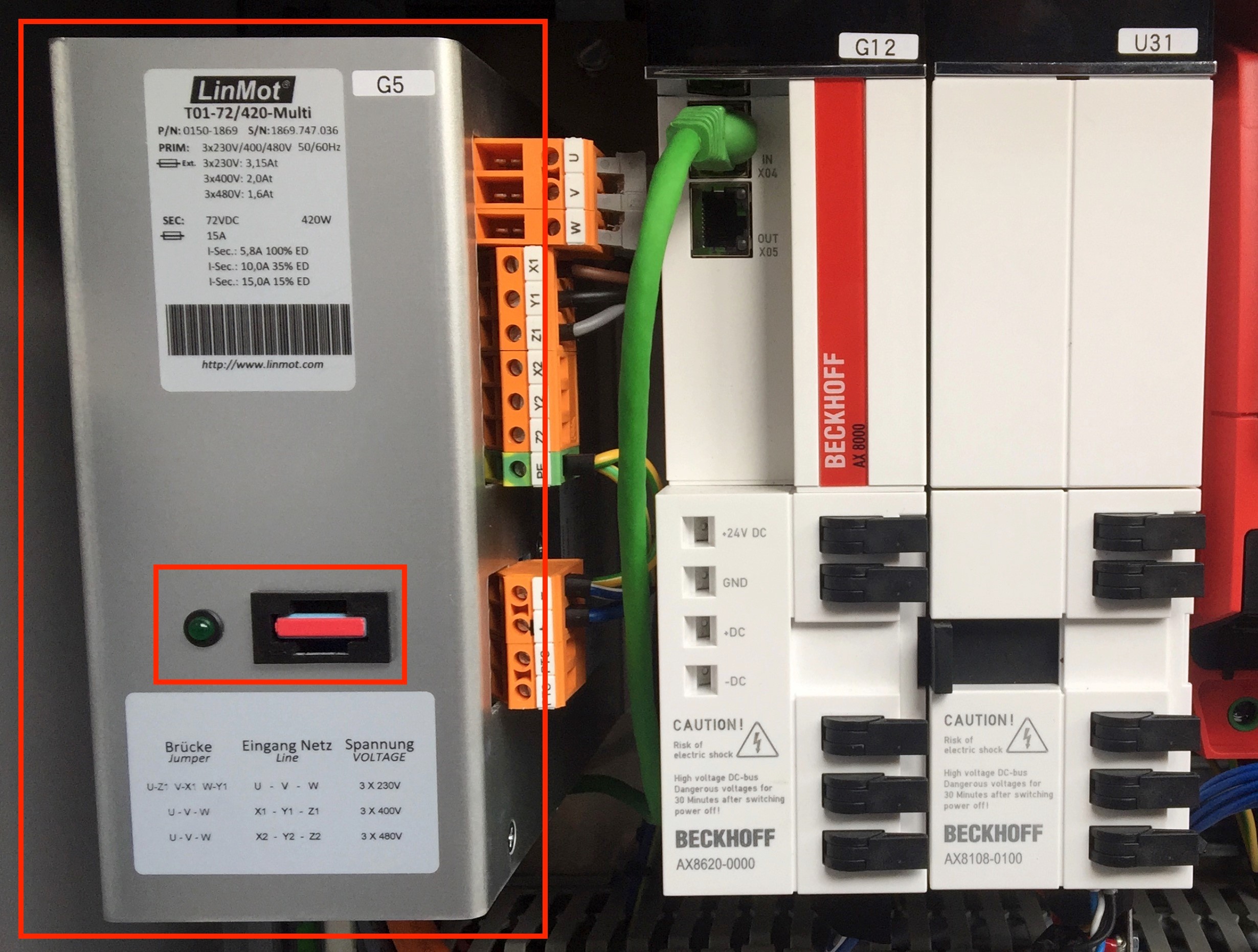
The main power supply 72 VDC of the Linmot controller is missing:
Check the power supply G5 inside the control panel on the second table (see attached picture). Most probably the 15 Amp. fuse is melted. Replace the broken fuse with a new one.
Problem:
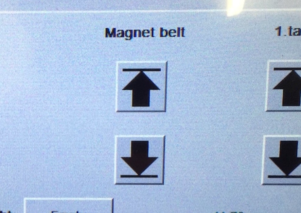
Error message „Magnet belt not down” displayed on HMI (magnet belt does only exist on the 2. table on a duplex slitter), and arrow buttons „Up” and „Down” for magnet belt are not visible anymore.
Possible Causes & Resolutions:
Arrow buttons magnet belt up may be visible for a short time and pushed during start up of panel.
Delete of error message:
Possible cause:
– bus connector limit switch not set correctly – address and dip switches not set according
to the electrical scheme (bus subscriber) – wire defect
– bus connector defect
– bus modul or subscriber defect.
To narrow the error you have to check the status with all the subscribers.
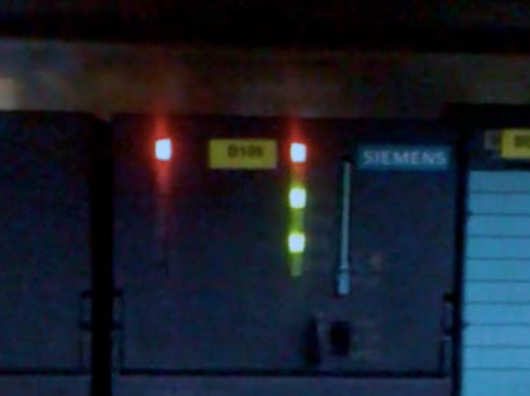
To test, switch the limit switch into the bus connector => the bus runs now to the corresponding subscriber, e.g. “Lenze inverter” which the LED flashes yellow.
If you are able to narrow in the error, exchange the corresponding components.

NOTE:
Do not forget to set the parameter and the dip switches accordingly. The parameters are mentioned in the electrical scheme!
BF LED (red) not active
Lenze inverter:
LED upper-left must light up (green)
LED upper-right must be flashing (yellow)
LinMot:
Error LED not active or no error code profibus

Beckhoff Control:
For the Beckhoff Control, please refer to this PDF for instructions.
Please refer to “User Manual Motion Control Software” for the error codes of the MC Software. The PROFIBUS Interface has the following additional error codes:
Error code hexadecimal: Error description: C1h Fatal error: Drive not supported
C2h Config error: Invalid MACID
C3h DP Err: Connection lost

Possible causes:
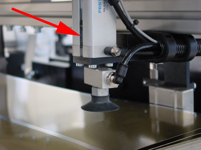
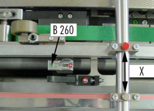
Make sure that the lateral, adjustable top guides (picture) are set correctly in lateral position as well as in height. They shall guide and hold the stripes as flat as possible over both sensors B260 and B261. Both sensors need to be reached at same time, otherwise the error will occur.
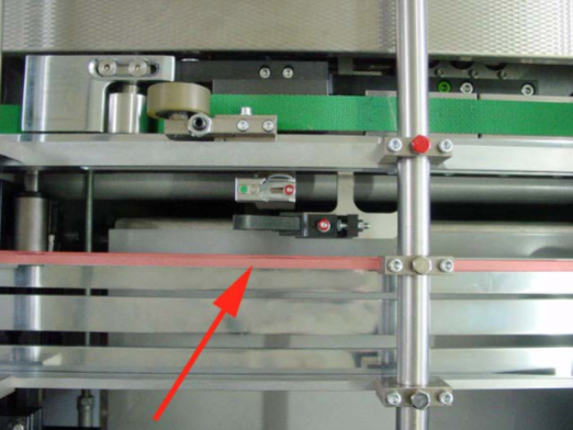
If the lateral guide is too far away from the sensor, the sheet might bulge. Therefore move the lateral guide closer to the sensor.
NOTE:
Do not loosen the screw marked red. The standard setting for top guide should be approx. X = 72 mm.
– Make sure that pressing rolls are adjusted correctly (picture).
– Check the movements of the sheet, they might get stuck somewhere.

Possible cause: