Support

5 Support Entries

Possible causes:

  • If your Big 8 slitter does have only one long magnetic rod-sensor, Big 8 cutting heads shall not touch each other, because the magnetic positioning rings (sitting around magnetic rod-sensor and mounted in each Big 8 unit), could interfear each other.
  • The amount of Big 8 units must always be equal with the amount of Big 8 icons shown on the display.

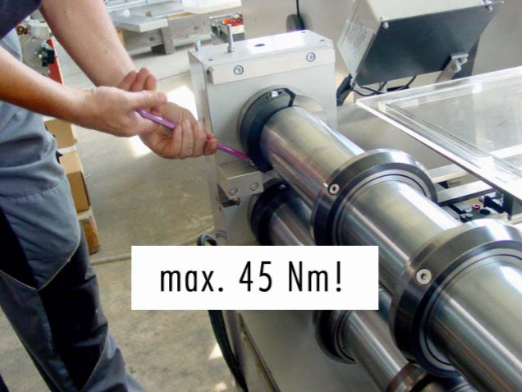
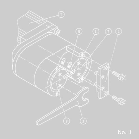
To remove the used cutting blades, two spherical clamp screws M6 (8) have to be loosened. The steps for the fitting of the fixing plate (4), which is part of the standard tools delivered with every slitter, are:

  1. Remove the plastic plate cover, 4 screws M5.
  2. Turn the cutter shaft (7) which is fitted to the drive motor (1) with the special tool (3) until the blade (2) is in the horizontal cutting position.
  3. Secure the direct driven cutter shaft (7) in this position with a fixing plate (4) against twisting. The fitting of the fixing plate (4) is done with 2 M5 screws which were used on the plastic plate cover.
  4. Release the clamp nut (6) of the not driven cutter shaft (9) with the special tool (3) and the point opening socket wrench (5).
    Use the same wrench (5) on the clamp nut (6) beside the drive motor (1). Turn clockwise = to grip
    Turn counterclockwise = to release
  5. Turn the released cutter shaft (9) until the blades are nearly closed together. Place a small piece of 0,02 mm tape between the blades. Turn the cutter shaft (9) until the tape is tied between the blades.
  6. In this position, the clamp nut (6) of the cutter shaft (9) should be tied up with the special tool (3) and the point opening socket wrench (5).
  7. Take away the tape and check that the cutter blades do not touch each other. Turn with the special tool (3), in the correct direction, with the motor driven cutter shaft (7). The ahead running blades should be in this cutter shaft.

Important
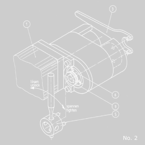
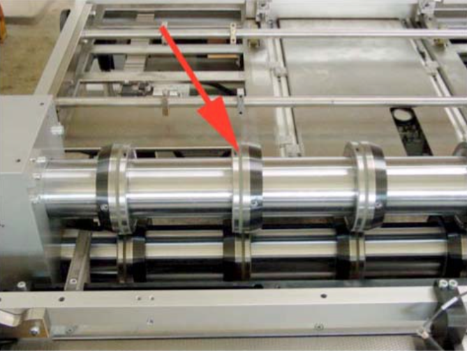
During the assembly of the new cutter blades (2) check that the ahead running blade is on the motor driven cutter shaft (7). See picture no. 3

Nobody should start the unit during the set up. The emergency button should be pressed down, the key-operated switch taken away from the slitter.

Non-compliance of this instruction will cause cutter blade damage or blocking of shafts.

Possible causes:

  • wrong cutter setting
  • cutters are blunt
    • grind your cutters
  • watch the sucker unit in front of the 1. cutting operation for too much downwards-bow of the sheet
    • adjust bottom stop
    • replace worn out sucker or parts
    • mount the full range of downholder rings – see picture below!
    • they prevent the bowing movement of the sheets

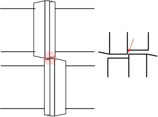
NOTE: The SQM measuring device can only detect “angular” cutting errors!

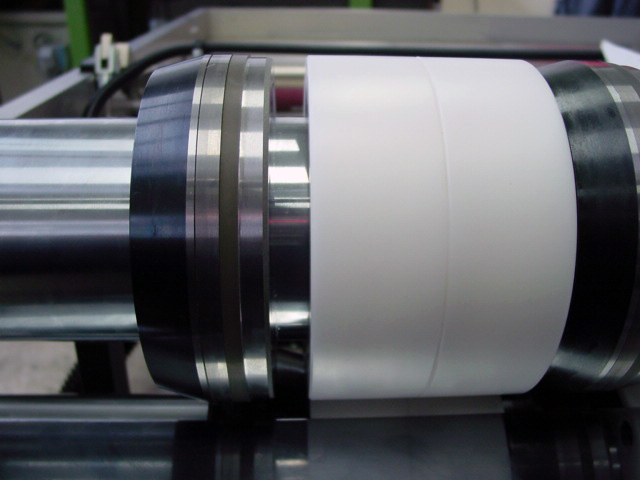
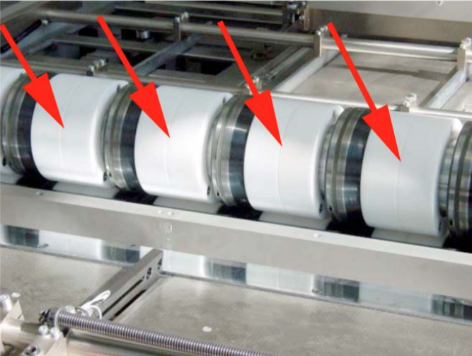
Check the transport rings on the knives: If the rubber is too small (due to heavy wear) conical or much bigger (if no original spares are in use) cutting tolerances can be negatively affected!


Make sure that enough support rings are mounted between the knives. They keep the sheet leveled. The thinner the sheets, the more important it is to keep them flat.


Make sure that all knives are well grinded.

NOTE:
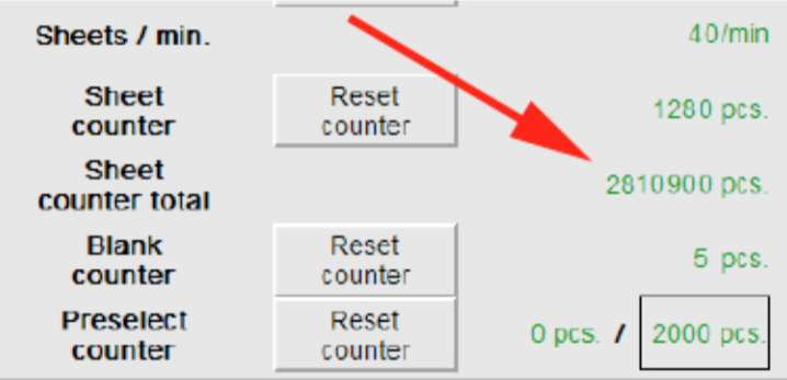
You should regrind your cutters after approx. 3 mio. sheets.


Possible causes:

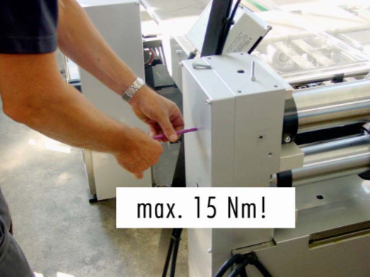
1. Clearance between the upper and lower cutter is too small – min. 1/100 mm.


2. The bearings of the roller cutter have play => they need to be free of play!

3. The roller cutter shaft is heating up differently!

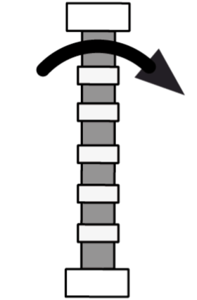
a) Something touches the roller cutter => slowly turn the roller cutter by hand

b) the bearing is heating up too much => bearing defect!


c) If you have an exchange roller cutter => the roller cutter shaft might not be fixed properly to the side.


=> or the roller cutter shaft is too tensely assembled!

All Can Man content is now also available on the Soudronic Group website.
Where do you want to continue your journey?
All Can Man content is now also available on the Soudronic Group website.
Where do you want to continue your journey?