Report all steps, new or different settings, old and new production parameters (can size, cpm, weld speed, weld current, weld frequency, current wave-form and transformer step) for an easier overview and follow-up!
Open a new ticket and add your document!
Note on which tin-plate parameters (thickness, hardness, tin coating inside / outside, rolling direction, BA or CA, supplier, printed or not) such faults occur, and on which tinplates not!
Basic parameters & settings to be checked first
- Tin-plates must be cutted within the allowed tolerances:
- Measure the tin-plates and report if out of tolerance!
- Follow sheet „blank-cutting tolerances“! Download PDF
- Are all tin-plate parameter clear and noted: Thickness, hardness, tin coating in and outside, rolling direction, BA or CA, supplier, printed or not
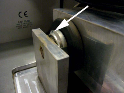
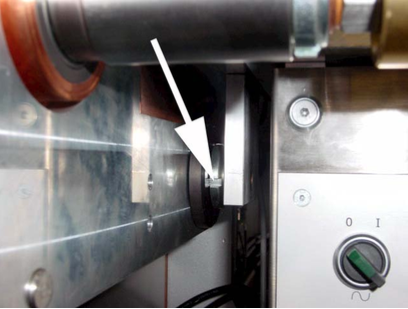
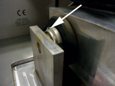
- The copper wire must be correct profiled and the surface not damaged:
- The width of the profiled copper wire shall always be 0.05 mm smaller than the profile-groove in the weld rollers!
- Measure the width of the profiled copper wire within around half a meter on several position, and note the variations. Maximum difference of 0.05 mm are allowed. If you measure more, check the concentricity of the profiling rings.
- Change the copper wire profiling rings or idler/guide wheels if the surface of the copper wire shows a damage!
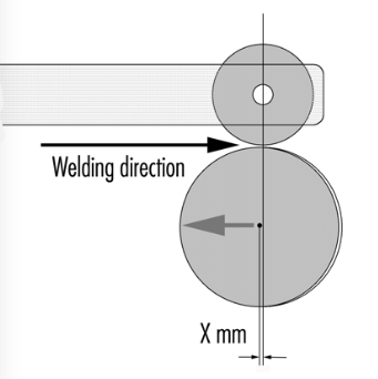
- Both weld rolls must be regrooved after its regular groove life-span or replaced:
- To avoid unexpected heavy weld faults it is recommended to implement the total piece-counter and the regrooving interval into the production order!
- As an example:
- Upper weld disc ø 90 mm to be regrooved after 3 mio cans (interval depends on, type of welder, type of weld roll and welding speed).
- Lower weld roll ø 62 mm to be regrooved after 2 mio cans.
- Total piece counter at production start at 28 mio welded can bodies, upper weld disc has been regrooved at 25 mio, therefore to be regrooved now! Lower weld roll regrooved at 27.5 mio, therefore to be regrooved at 29.5 mio.
- After every regrooving weld roll and / or z-bar must be repositioned: Use the correct to reset the lower weld roll and/or nose-piece, and the upper welding roller!
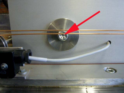
- The z-bar must be clean in and outside – and not worn -, calibration crown must be clean, and are all pre-calibration rollers shall turning easily:
- A dirty z-bar may not be well insulated, therefore the risk of wear is higher and the weld current is flowing over z-bar and tin-plate to the weld center!
- Note: The insulation of the secondary circuit should be controlled yearly!
- Non turning pre-calibration rollers can create body-offset and unconstant can gap!
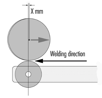
- Both tin-layers must be centered and parallel on the copper wire:
- That means that all mechanical settings are correct!
- The welding pressure must be set correct:
- Welding pressure for Wima welders vary between 35 and 50 kg / daN. Start with ~ 45 kg / daN. Check the manual to convert in bars.
- 50 Hz welder using welding pressures between 35 – 45 kg/daN, while automatic welders running between 40 – 50 kg / daN.
- The welded overlap must be correct, and on begin and end within allowed tolerance:
- Correct welded overlap depending on z-bar:
- Z-bar of 0.4 mm results in a welded overlap of 0.5 – 0.6 mm
- Z-bar of 0.6 mm results in a welded overlap of 0.7 – 0.8 mm
- Z-bar of 0.8 mm results in a welded overlap of 0.9 – 1.0 mm
- If the overlap is not correct, adjust until overlap is correct:
- Reset the calibration crown if needed with the mandrel. The diabolo-rollers should not have any radial-play!
- Adjust the overlap according manual.
- Once the overlap has been set, double check and set the can gap. Increasing the overlap will reduce the can gap, decreasing the overlap will increase the can gap.
- Weld around 5 cans and measure the gap between the tin-layers. A good can gap measures between 1.5 – 3.0 mm. Any variation should be within 0.5 – 1.0 mm.
- The main weld current must be set correct!
- How to do:
- Reduce weld current until cold weld zones appear. Tear-off test must be done at an angle of 30 – 45°, means try to pull-off the top tin plate edge. To be done from each side. Note the weld current value!
- Increase weld current until hot weld appears. Tear-off test must be done at an angle of 0°, means pull-off the seam only and find out when the seam starts to become fragile. Note the weld current value!
- Add 2/3 of the weld current difference between cold and hot weld seam to the cold weld seam value, and start the production!
- Set beginning and end time and beginning and end current!
- Note: If the welder is running with triangle wave-form, make sure the duty-cycle is between 80 – 90%. If the welder is running with sine wave-form, make sure the right transformer step has been choosen! Contact us if you are not sure.
- The seam-extrusion inside and outside must be equal!
- If the seam extrusion is bigger inside, reduce the height of the calibration crown. If the seam extrusion is bigger outside, increase the height of the calibration crown.
- The shape or roundness of the can-body is not so important as a correct seam-extrusion!
- The seam extrusion inside depend on the inner weld roll diameter as well: The diameter difference of upper and lower weld roll should be as small as possible.