Support

14 Support Entries

Problem:

Machine stops and message „Pacemaker: Profibus communication error“ is displayed.

Possible Causes & Resolutions:

  • Cooling water valve: Wrong type of valve or plug without protective circuit (suppressor). The voltage peaks can cause interferences in the Pacemaker electronics. Always use the original plug and valve type.
  • Profibus plug: On the plug of first and last client of profibus system the termination resistant must be set to ON. Otherwise interference may occur.
  • Profibus cables: Check the position of the cables in the control unit. If they are close to contactors, high voltage peaks can create interferences.

Download PDF here

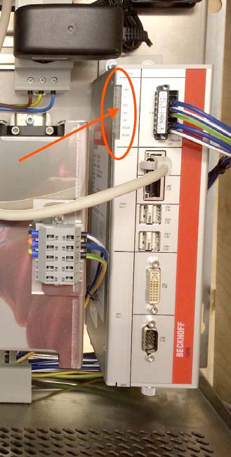
Click here for the status LED’s of the Beckhoff PC and how to access the PC in case of a trouble shooting.


  • If the Led are not switching off after machine power off (wait at least 5min. !), remove the X101 plug on the IPC and plug it back after some seconds.


Possible cause:

  • The setting of the magazine is wrong
  • The separating air is not correctly set, or the air pressure is too low
  • Too much tin plates – especially on can heights over 200 mm:
    • in the magazine, the weight is too high!
  • Tin plates have too much burrs
  • Suckers are worn
  • Sucker height too low
  • Linmot slider is not well positioned:
    • Pusher plate must stay around 2 mm behind the tin plates
  • No signal of tool sensor B6:
    • Maybe gap between can body and sensor to big?
    • Maybe wire break and no signal on plc/pacemaker. Check cable and plug!

Download PDF here

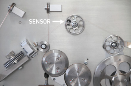
The error occures when there is a problem with the measurement of the wire speed (not wire speed by self).

  • Check the gap between idler wheel and sensor, 1mm is recommended!
  • Check the bearings of the idler wheel! Is turning smoothly? To much play can create an unstable gap to the sensor.
  • Check cable between sensor and plc!

If there is still a problem with the measurement of wire speed, you can proceed as follows to restart production:

  1. Push the “Key button” on home screen
  2. Login with your password ****
  3. Push again the “Key button” to reach the setting window
  4. There you can find a second “Key button”. Push that button to reach the main setting window.
  5. There you can find on right top position a button “Wire speed control”
  6. Switch this funktion to ”OFF”

Please note: The workaround described above is not recommended for permanent production!

  • Check first whether the conveyor / elevator unit is blocked somewhere!
  • Check the 24 VDC fuse according electrical diagram. Make sure that the correct size will be used!
  • Check the setting of the respective sensor (according electrical diagram), which allows the conveyor to move if the sensor is active / free!
  • Take the 24 VDC motor out, and check whether the motor is defective or not! Make sure that the conveyor is not moving downwards as soon as the mechanical connection between motor and elevator unit has been released!

P03 = positioning countering error

Possible causes:

  • Resolver on the backside of the bodytransport motor is damaged.
    • Check if the bearings are worn out!
  • Resolver is not fixed well on the shaft.
    • Fix it!
  • Wire break in the cable between resolver and servo controller.
    • Check the cable!

Possible cause:

Possible cause/checklist:

  1. Position Linmot pusher plate:
    Must be 1 mm behind tin plate edge!
  2. Adjust roller clearance on all 7 pairs according manual.
  3. First roller pair:
    If you can’t get 0.1 mm roll clearance, check the toothed gears inside/outside. They may have a wrong lateral position; that ends in a too big clearance between the shafts!
  4. Test after setting:
    Take off main and inner timing belt, rollers touching each other, all gears must have slight play!
  5. Check and adjust a well rollformed canbody:
    Form of canbody must be round, both edges must have a parallel overlap, depending on the diameter!
    – Diameter 52 mm = approx. 5 mm
    – Diameter 99 mm = approx. 20 mm
  6. Check the feeder angle and rollformer speed according the recipe of the canbody you are currently running.
    NOTE: «If parameter is different from recipe, it has been changed without authorization of Can Man! Any guarantee claims will be refused!»
  7. Check the curve you have in the tuning window with the recipe of the canbody you are currently running.
    NOTE: «If parameter is different from recipe, it has been changed without authorization of Can Man! Any guarantee claims will be refused!»
  8. Make sure you have mounted the correct pair of final pusher fingers (see the diameter range engraved on the fingers).
  9. Check the actual overtravel with the help of the manual.

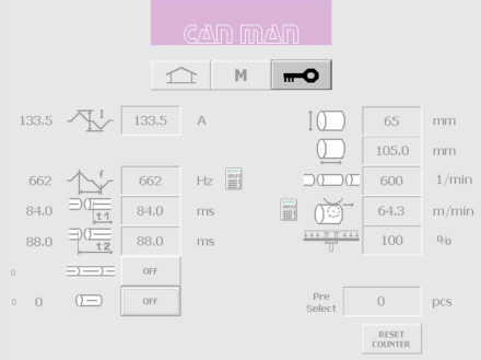
The recipe helps to adapt the speed of the incoming can into welding roller and the actual welding speed. In the best case, those speeds are equal.

Below you find a table of this recipe in steps of 10 mm can height.

Turn the wheel of the synchrostar, that the pusher finger is as close as possible to the welding roll.

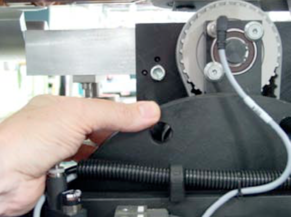
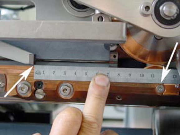
Measure now the distance from the top of the pusher finger to the center of the welding roll.

Distance = Can height – Overtravel Example:
Canheight: 122mm Overtravel: 4.8 mm

Distance: 117.2 mm

Possible cause:

This problem occurs, if the main switch of machine is turned on, but the machine is not running production for a longer period. The cooling plate of servo drive is heating up, because the water valve is turned off during this time, to prevent condensation water.

Turn off the main switch, if you don’t run the machine for a longer time.
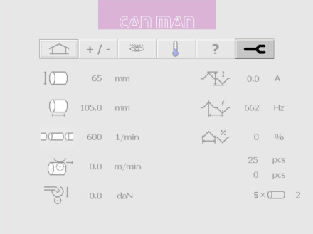
To get rid off the error with overtemp. servo drives you can go to the „Tuning page“. Press the button to switch on the main valve for the cooling system manually. Keep this button pressed for a few minutes, the system will cool down and you can start the machine normally. If you close the “Tuning page”, the main valve is switching back to automatic mode, controlled by „Production ON/OFF“.

Possible cause:

  • Drives for the height change magazin and infeed system are active and stopped before reaching the position – overcurrent active.
    • Go to the mask for height change, push the reset button and the start button. The drives must reach the position without overcurrent message. If the error comes again, check the free movement of mechanical system.
  • If “SF” and “BF” on the PLC are “Red”, some drives on profibus are missing (no connection of height change position drive to profibus).
    • Check Fuse F6/F7!
    • End resistant of all profibus plugs must be “OFF”, only first and last plug “ON”.
    • Open the profibus plug on height change positioning drives, then open and close again the connectors!
    • Check the profibus cables!
    • Check the profibus module for damages or bad contacts!

Possible cause:

  • Since the slider of the linear motor contains strong magnets, remove dust or small particles from slider with a disposable paper.
  • Make sure that you have a clearance of 0.1 – 0.2 mm between the pusher plate and the vacuum plate.


Possible cause:

  • Check the air pressure on the small air regulator, the value must be around 0.5bar (pressure to engage the clutch).
    • refer also to the touch screen “Air” symbol, where you find the exact values.
  • Check the air pressure on the precision air regulator, left side from synchrostar motor, to 1.6 to 2.0 bar (pressure to disengage the clutch)
    • refer again to the touch screen “Air” symbol.
  • Check whether the safety clutch is engaged or not: Turn the synchrostar by hand, and see whether the motor is also turning or not. If yes, the clutch is engaged!
  • If the clutch is engaged, but the error message still remains, the sensor B69 might wrong positioned:
    • Check if the LED from the sensor is OFF.
    • If the LED is still ON, turn the sensor a quarter turn counterclockwise, or until the LED is OFF. Do not turn the sensor too much counterclockwise. If the distance is too big the clutch does not stop the machine in case of a crash. To test you can adjust the precision air regulator of clutch to „0“. Now the clutch is disengaged and the sensor has to be ON.
    • Make sure that the sensor has still a clearance of about 0.5mm refer to manual Mayr EAS 450  or Mayr Clutch 0-481-325
    • Turn the synchrostar and make sure that there is no resistance coming from the sensor/clutch!
All Can Man content is now also available on the Soudronic Group website.
Where do you want to continue your journey?
All Can Man content is now also available on the Soudronic Group website.
Where do you want to continue your journey?