Support

11 Support Entries

Problem:

Circuit breaker Q5 trips when the machine is switched on or during production.

Possible Causes or Resolutions:

  • Measure voltages at all phases, even under load. It is possible that one phase did drop down, and this triggered the circuit breaker.
  • Measure the current of each phase with a current clamp after Q5. If the measured value is below the value of the circuit breaker and Q5 still keeps tripping, the circuit breaker may be defective. Replace it.
  • Maybe the parameter “Low bat voltage” (coming from Pacemaker) is set too low: That means that the contactor in the Pacemaker closes too early with a precharge voltage that is too low and therefore Q5 trips. To check this, please open a ticket to contact CanMan.

Problem:

All drives are starting correctly, but the vacuum and welding current are not active.

Possible Causes & Resolutions:

  • Welding pressure has been set below the min. value of 2.0 bar => Check the welding pressure setting value on the precise air-regulator and reset if needed.
  • Solenoid valve welding pressure Y10 does not work correctly  => Check the welding pressure valve Y10. Does the valve switch correctly and do the welding rollers close?
  • Welding rollers are closing and welding pressure is set correct, but no welding pressure value is displayed on the HMI => Check whether the analogue sensor B77 is working correctly or not.


Problem:

After main switch off and on again, HMI piece counter values and settings are lost or old recipes are loaded.

Possible Causes & Resolutions:

  • IPC has not shut down correctly.Check the IPC after you switched off the main switch: Normally it will continue to run for at least 30 seconds to shut down correctly. If LED’s of IPC goes off within a few second, the battery of the UPS – unit is dead and needs to be replaced.


Problem:

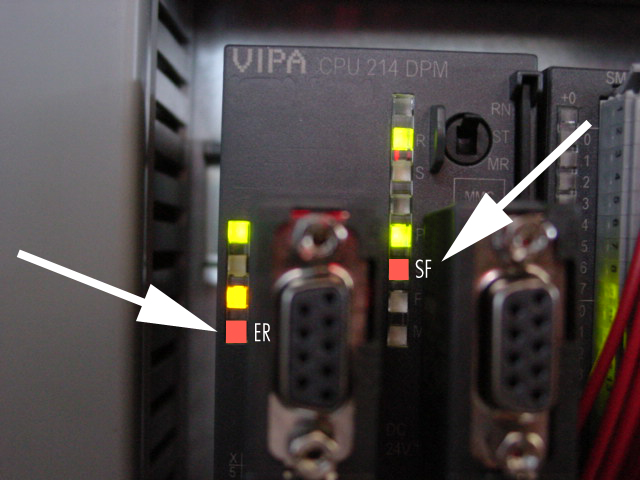
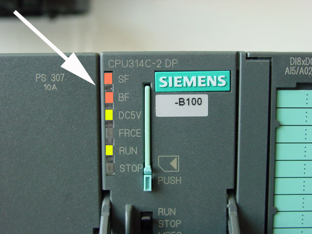
Machine stops and message „Pacemaker: Profibus communication error“ is displayed.

Possible Causes & Resolutions:

  • Cooling water valve: Wrong type of valve or plug without protective circuit (suppressor). The voltage peaks can cause interferences in the Pacemaker electronics. Always use the original plug and valve type.
  • Profibus plug: On the plug of first and last client of profibus system the termination resistant must be set to ON. Otherwise interference may occur.
  • Profibus cables: Check the position of the cables in the control unit. If they are close to contactors, high voltage peaks can create interferences.

Problem:

  • Speed of the drives changes during production


Possible causes & resolutions:

  • Wrong position of the switch for the terminating resistor on the bus plug.
    Check all switches on the complete bus system. Follow the cable thoroughly from first DP bus device (PLC) to last DP bus device. The terminating resistor switch of first and last must be set to „ON”, all other to „OFF“.
  • Bus connector/plug defect
  • Check wiring of all profibus cables, especially the connection of the cable shield inside the plug.
  • Problem of terminating resistor supply by last device on bus. Try to change the profibus wiring to use on another device as last client.


  • The fan unit can be removed. Check whether the fan is correctly mounted (screwed).
  • The fans can also be removed and cleaned if dirty.
  • Replace the defective fan unit!


Download PDF

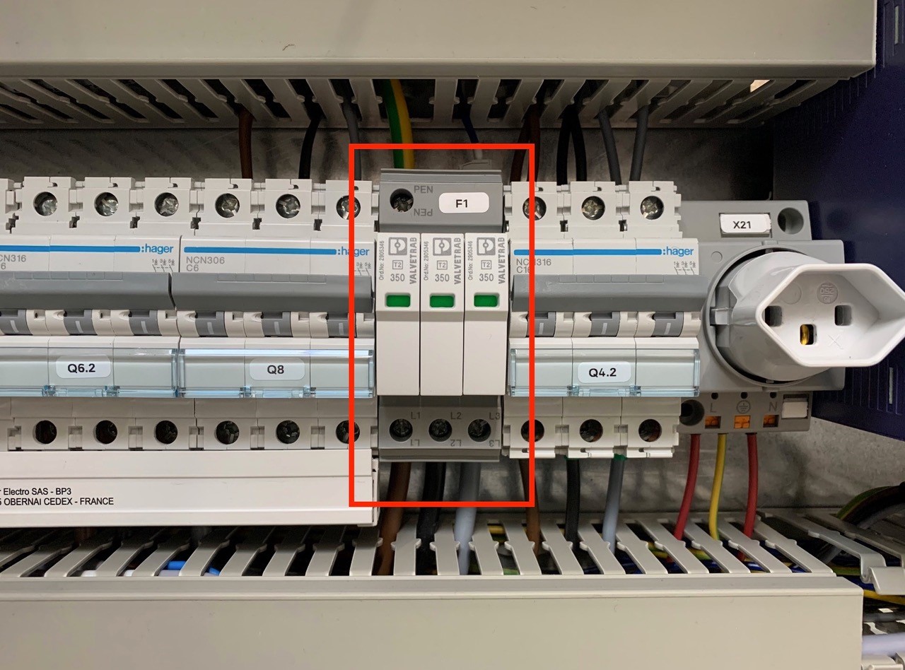
An overvoltage suppressor (or surge suppressor) is an appliance designed to protect electrical devices from voltage spikes. A surge suppressor attempts to regulate the voltage supplied to an electric device by either blocking or by shorting to ground voltages above a safe threshold.

These surge suppressors are built in to the latest Pacemaker models and machine controls (from 2009).

Check, if one or more modules of the surge suppressors are red/defect. Replace the red modules.

Attention!!!

Do not bridge the signalling contacts and run the machine with defective red modules because they no longer protect the system from voltage peaks!!!
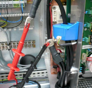
If the modules are defective, check the main supply. Measure and check all voltages between the phases and all phases to earth before exchange the modules and restart the machine.

  1. Switch off the main switch Q1 of the machine.
  2. Wait around 10min before you do anything on the wiring of the pacemaker! The capacitors need that time to discharge!!!
  3. Disconnect both welding cables from Pacemaker.
  4. Measure the resistant of both cable to earth. If the value is very low maybe the transformer primary side have short circuit to earth or the cables are damaged and make some contact to earth. If it looks ok (endless or very high resistant) go to point 5.
  5. Take the welding copper wire completely out of welder.
  6. Control that pendulum roller head is lift up. Put a carton or another insulating material between both welding rollers to make sure that you don’t have any contact between the rollers.
  7. Connect an external cable 230VAC (phase and neutral) to the welding cables, which you have removed on pacemaker before. Use for this external supply a 10A fuse breaker to protect the supply in case of a short circuit of welding transformer. (Take a look to picture on point 3)
  8. Before you switch on the external supply check again:
    – Wire removed?
    – Pendelum rollerhead lift up and isolation between welding rollers?
  9. Now switch on the external supply. If the 10A fuse breaker does not trip it is a good sign and it doesn’t look like short circuit of welding transformer.
  10. To control the output of welding transformer you can measure the voltage between the welding rolls (VAC). The measured voltage is depending on the type of welding transformer. If you change the transformer step this value has also to change. Check the output voltage of each step. Don’t worry if you measure only around 5VAC, the output voltage of welding transformer is a low voltage.

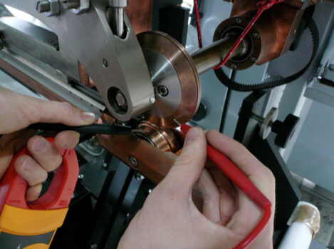
Before you change the transformer step switch off first the external supply!!!


Download PDF english

Download PDF chinese

Possible cause:

This problem occurs, if the main switch of machine is turned on, but the machine is not running production for a longer period. The cooling plate of servo drive is heating up, because the water valve is turned off during this time, to prevent condensation water.

Turn off the main switch, if you don’t run the machine for a longer time.
To get rid off the error with overtemp. servo drives you can go to the „Tuning page“. Press the button to switch on the main valve for the cooling system manually. Keep this button pressed for a few minutes, the system will cool down and you can start the machine normally. If you close the “Tuning page”, the main valve is switching back to automatic mode, controlled by „Production ON/OFF“.

The instructions below show you how to connect the following signals: a) Line control b) Error powder unit and c) Release powder

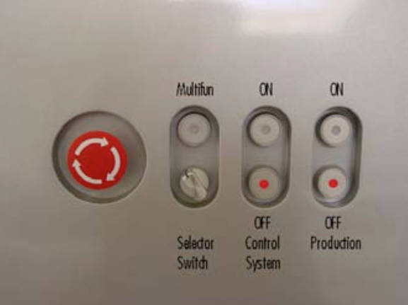
Signal: line control


In order to switch off the downline due to an error, the PLC has a prepared input. To use this input, we need a potential-free signal from the downline, which is closed when the line is ready. Use the terminal E5.1 to connect the line control.


As soon as an error occurs, the destacking of the sheets stops and after an adjustable delay the wire-run and the remaining drives. The canbody transport continues to run slowly. This mode plus the flashing of the key „Production ON“ shows the operator the status of the line stop.


ATTENTION:
Machine begins to produce independently again, respectively after the release of the line control.


This input should be connected the same way as the line control. Here as well we need a potential-free relay contact of the powder unit. But this contact needs to be open, if there is any error. This signal needs to be connected to E126.7.

The production shuts off, if an error occurs. After that the operator needs to switch on the machine.


Signal: Release powder


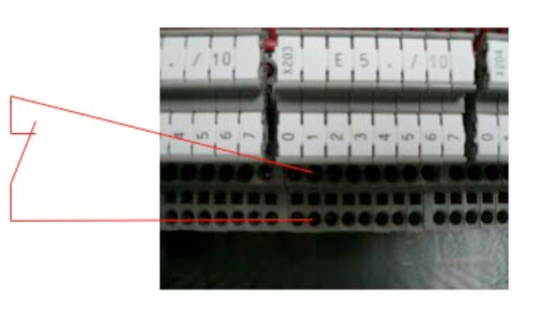
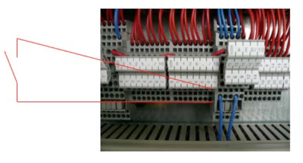
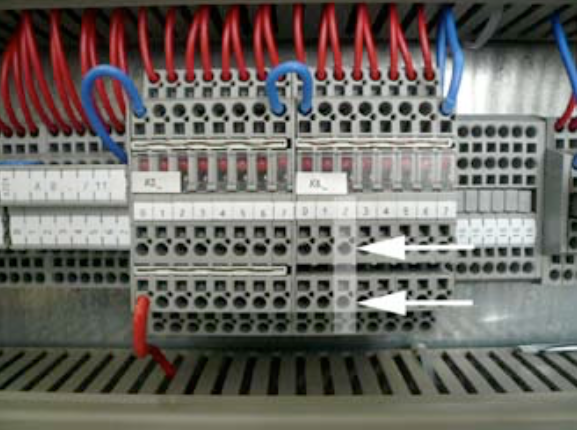
In order to switch on the powder, we provide a change-over contact. The contact switches as soon as the production or a single can is triggered. In order to provide enough time for the initialization of the powder, the destacking is delayed by an adjustable time. Before you connect this signal, you have to remove the comb bridge (1) and the link (2), in order to make the contact potential-free.


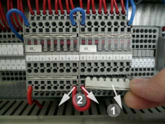
Use the terminal K6.2 (A124.2).


NOTE:
Consult the electrical scheme of your welder to double-check the various input signals. In case you are not successful with the connection, contact a CAN MAN electrician.


Possible causes:

  • No supply of a slave on the bus system.
    • Check supply of all slaves.
      Emergency stop must be released.
  • Address of slave on Profibus is wrongly adjusted.
    • Check setting of all DIP switches on the Lenze bus module and on the Linmot controller.
      You can find the correct setting on the wiring diagram.
  • Wrong position of the switch for end resistant on the bus plug.
    • Check all switches on the complete bus system. Seriously follow the cable from PLC to the last slave. First plug and plug of last slave must be set to ON, all other plugs to OFF.

All Can Man content is now also available on the Soudronic Group website.
Where do you want to continue your journey?
All Can Man content is now also available on the Soudronic Group website.
Where do you want to continue your journey?