Problem:
Circuit breaker Q5 trips when the machine is switched on or during production.
Possible Causes or Resolutions:
Problem:
All drives are starting correctly, but the vacuum and welding current are not active.
Possible Causes & Resolutions:
Problem:
After main switch off and on again, HMI piece counter values and settings are lost or old recipes are loaded.
Possible Causes & Resolutions:
Problem:
Downstacker motor doesn’t move correctly to the reference position, stops or suddenly changes the direction of rotation. Display of servo controller U16 shows „IMax“ or „P03 trip“.
Possible Causes & Resolutions:
To check:
Problem:
Machine stops and message „Pacemaker: Profibus communication error“ is displayed.
Possible Causes & Resolutions:
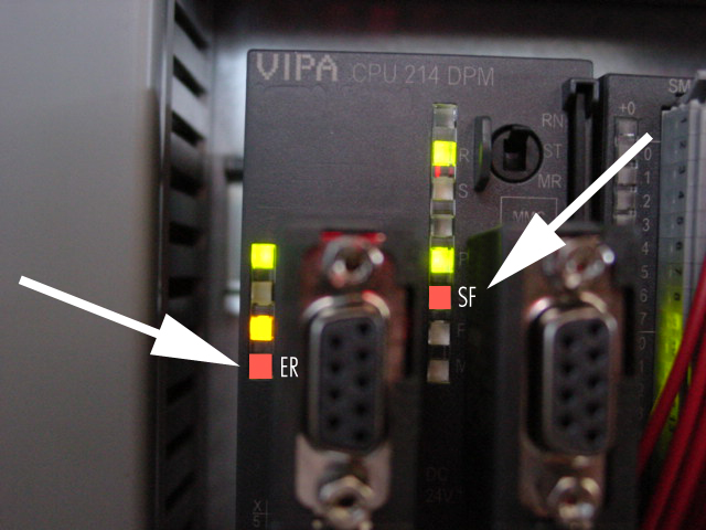
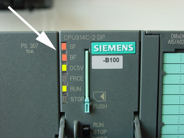
Problem:
Possible causes & resolutions:
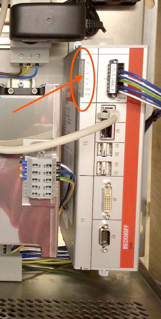
Click here for the status LED’s of the Beckhoff PC and how to access the PC in case of a trouble shooting.
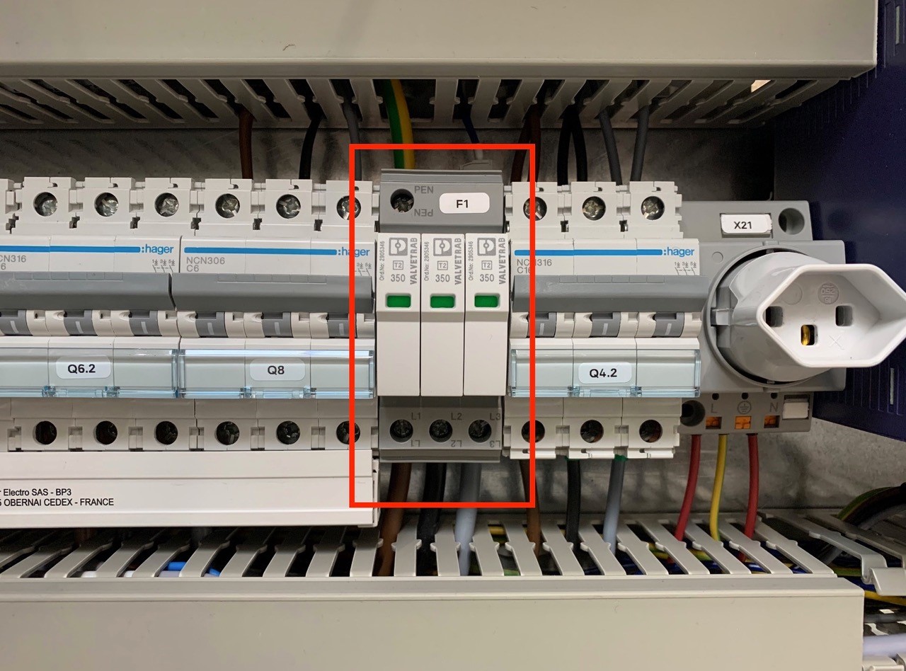
An overvoltage suppressor (or surge suppressor) is an appliance designed to protect electrical devices from voltage spikes. A surge suppressor attempts to regulate the voltage supplied to an electric device by either blocking or by shorting to ground voltages above a safe threshold.
These surge suppressors are built in to the latest Pacemaker models and machine controls (from 2009).
Check, if one or more modules of the surge suppressors are red/defect. Replace the red modules.
Attention!!!
Do not bridge the signalling contacts and run the machine with defective red modules because they no longer protect the system from voltage peaks!!!
If the modules are defective, check the main supply. Measure and check all voltages between the phases and all phases to earth before exchange the modules and restart the machine.
Possible cause:
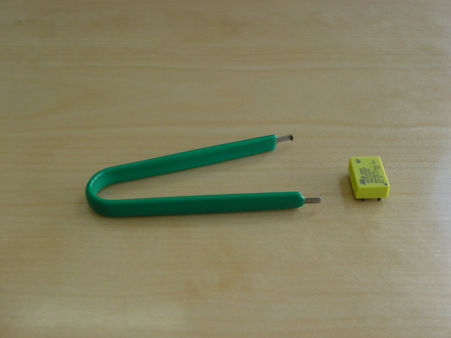
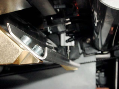
1 or 2 (sender/receiver) sensors are fitted behind the first pair of rollers to recognize double sheets.
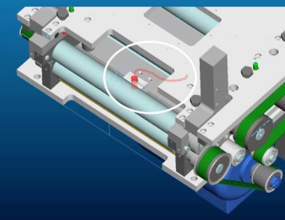
Sensor in the lower part.
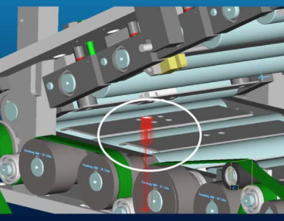
A pneumatic cylinder operates the ejection flap.
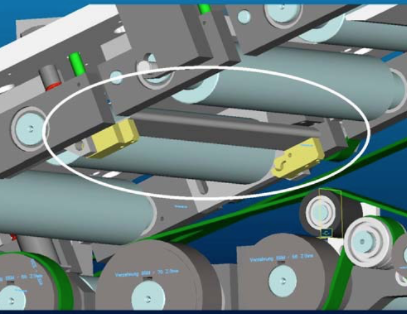
The double sheets detected by the sensor are diverted into this channel by means of a switch point.
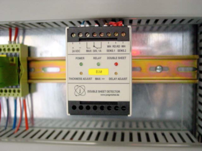
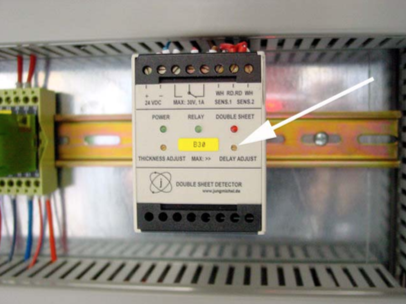
Setting the double sheet sensor
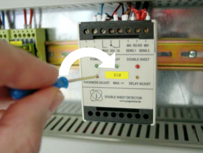
B30
The evaluation unit for the double sheet sensor is located in either the control box (illustration) or in the immediate vicinity of the rollformer, on the feeder side.
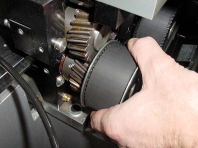
To set the sheet thickness, take a single sheet and lay it on the support rails in front of the first roller pair. You can also open the roll- former and lay a sheet into the rear area by hand. Then close the rollformer again.
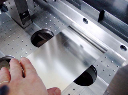
Now turn the single sheet back and forward in the first roller pair by hand with the help of the belt.
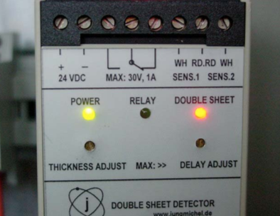
The two green LEDs „Power“ and „Relay“ should now be lit up on the evaluation unit.
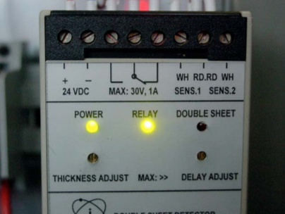
If the red LED „Double sheet“ is lit up, you must carry out a correction.
Turn the left-hand screw „Thickness Adjust“ clockwise until the red LED goes out and the green LED „Relay“ lights up. Add 1-2 additional turns in the clockwise direction.
Now carry out the same procedure with two sheets (double sheet).
The red LED „Double sheet“ should now be lit up.
The cylinder should now also be activated. It will be reset again when the sheets are removed.
Do not turn the right-hand screw „Delay adjust“; this is used for the delay of the cylinder stroke.
NOTE:
You will find further details in Book 5 OEM manuals on the CD.
Possible cause:
Possible causes:
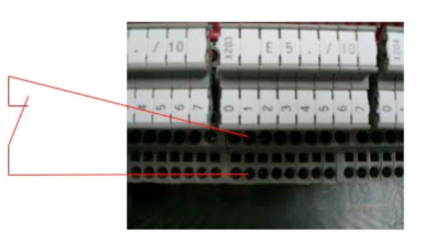
The instructions below show you how to connect the following signals: a) Line control b) Error powder unit and c) Release powder
Signal: line control
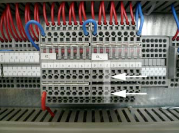
In order to switch off the downline due to an error, the PLC has a prepared input. To use this input, we need a potential-free signal from the downline, which is closed when the line is ready. Use the terminal E5.1 to connect the line control.
As soon as an error occurs, the destacking of the sheets stops and after an adjustable delay the wire-run and the remaining drives. The canbody transport continues to run slowly. This mode plus the flashing of the key „Production ON“ shows the operator the status of the line stop.
ATTENTION:
Machine begins to produce independently again, respectively after the release of the line control.
This input should be connected the same way as the line control. Here as well we need a potential-free relay contact of the powder unit. But this contact needs to be open, if there is any error. This signal needs to be connected to E126.7.
The production shuts off, if an error occurs. After that the operator needs to switch on the machine.
Signal: Release powder
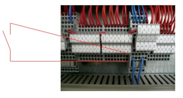
In order to switch on the powder, we provide a change-over contact. The contact switches as soon as the production or a single can is triggered. In order to provide enough time for the initialization of the powder, the destacking is delayed by an adjustable time. Before you connect this signal, you have to remove the comb bridge (1) and the link (2), in order to make the contact potential-free.
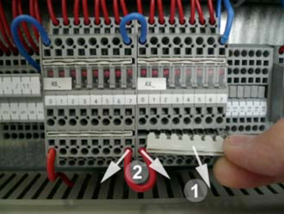
Use the terminal K6.2 (A124.2).
NOTE:
Consult the electrical scheme of your welder to double-check the various input signals. In case you are not successful with the connection, contact a CAN MAN electrician.
Cause 1:
The setting of t1 and t2 is wrong. If the timing is wrong the PM cannot execute the signal, which is necessary to memorize the canbodies in the reject unit and to start the record of the graph.
Setting of t1 and t2:
t1 defines the starting point for the reduced current time window. ![]()
t2 is the time, where the reduced current windows ends. t2–t1= thus is the timespan for the reduced current, therefore t2 > t1! ![]()
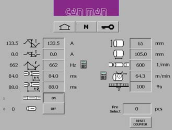
NOTE:
The value of t2 and t1 needs to be smaller as the cycle of one single can.
For example:
A production of 300/min. corresponds to a cycle time of 200 ms/can. Production of 600/min. corresponds to 100ms/can.
NOTE:
For a more detailed explanation of timing t1 and t2, consult your manual book 2, chapter 5.6.5. “Setting of Parameter t1 & t2 for reduced Current and Overlap Check“.
Cause 2:
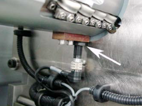
Check the inductive proximity switch B64 at the final pusher unit for function, operating distance and defect.
B64
Final pusher (Synchrostar II): Sensor B64.
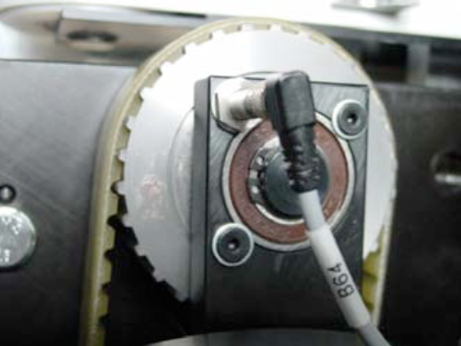
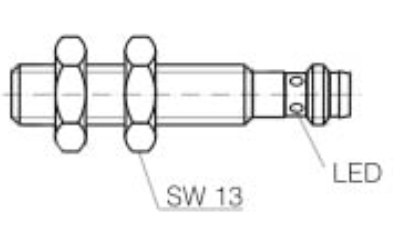
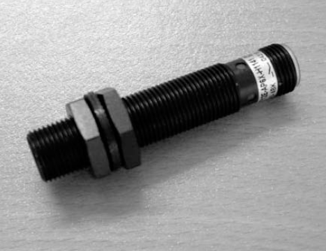
Description:
Inductive proximity sensor for embeddable mounting.
Polarity: PNP
Output: NO. or NC.
Operating distance: 2mm
Cause 3:
Check the tool switch B6 in the calibration tool for function, operating distance and defect.
B6
The position of the welding sensor B6, can be almost flush. Just make sure that you do not get scratches on the canbodies.
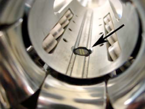
The height of the sensor can be adjusted here (see arrow).
Inductive Sensor (magnetic field resistant)
Mounting mode: flush
Function principle: inductive/normally open Rated operating distance: 3 mm
Find a complete error list together with the interpretation of the error codes
Download PDF here
Possible causes:
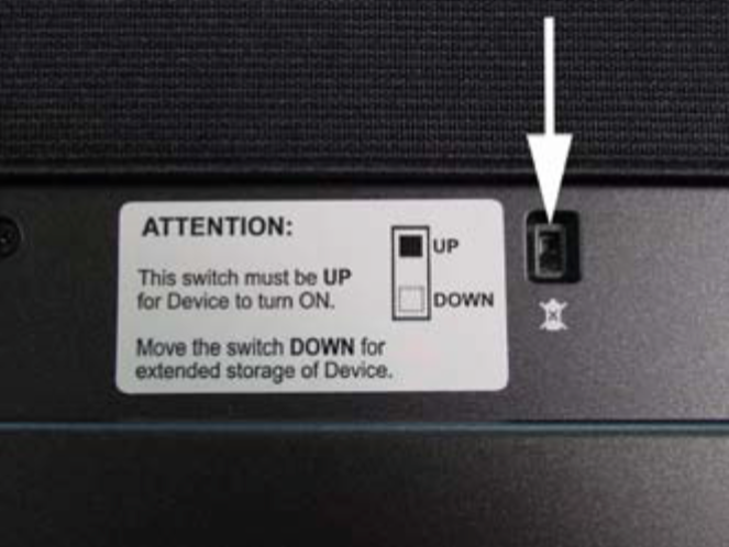
NOTE:
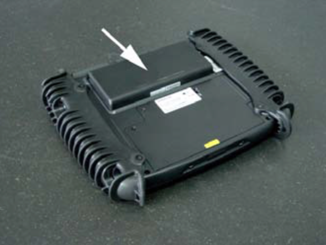
If you do not use the panel for a longer period (several weeks), the device should be turned off on the backside. Otherwise the internal battery will discharge and will get damaged!
If you push the button on the right side, you are able to see the status of the integrated battery and optional available second battery.
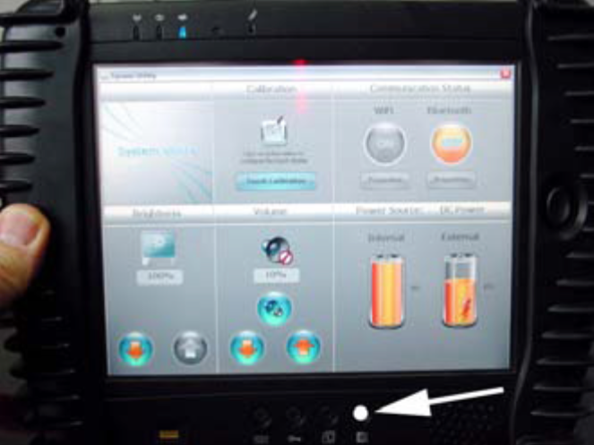
The optional second battery is located at the back of the device.