Support

5 Support Entries

Possible cause:

  • Maintain the calibration crown according to the manual (Book 2; chapter 5.5.4.)
    Important: All precalibration rollers must turn smoothly, not one should be blocked.
  • Reset the calibration crown according Resetting of the tooling
  • Guideline: The higher the production speed, the more difficult to control body offset issues!
  • Tin deposit on z-bar grooves
  • Rollforming not enough

Special settings:

  • The setting of the first, second and probably third spring tensioned rollers before the diabolo roller crown may vary in setting.
  • Basic setting – first, second and – depend on can height – also third rollers should have 0.10 mm movement.
  • If the body offset still remain, start to undo all the nuts of the first pre-calibration rollers by a sixth turn, and so on.
  • Check whether the Z-bar grooves are clean or full of tin/steel pick up:
    • If the grooves are full, clean them by sandpaper 400 or higher. For better cleaning take off the lower welding arm completely. Switch off the chiller before start to dismantle!
    • Check the insulation according manual – How to do an insulation check (yearly task)?
    • Check whether the secondary circuit – lower arm side – is connected to ground by a separate green/yellow cable!

Download PDF here

Possible causes:

  • Tool plug not properly connected.
  • Plug wet or humid.
    • Blow out and dry the plug.
  • Short-circuit from the diabolo rolls or precalibration to the mounting plate. Due to the temperature sensor cables, which are guided through mounting plate, an error message could be triggered through induction.
    • Dispose the short-circuit and clean the tooling from welding spillings. Use a contact spray.

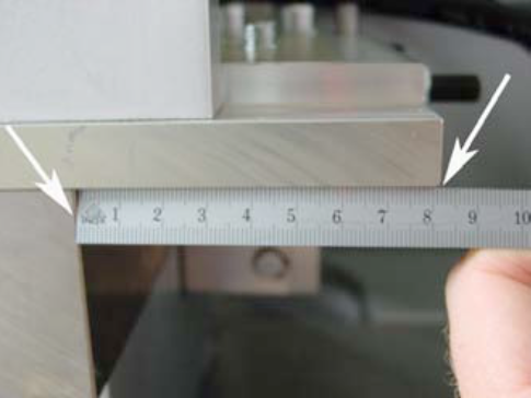
The center of the calibration crown (tooling) should be X = 2 – 3 mm behind the center of the pendulum roller head.


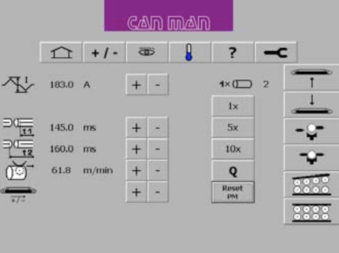
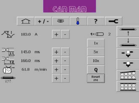
To adjust the position, tip the „tool out“ symbol.  


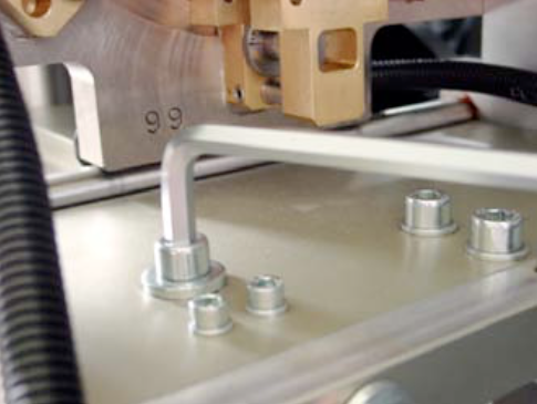
Then you have to loosen the two M10 screws on top of the tooling plate.


Then you loosen the M6 counternut (1) below the plate, then you can adjust the position with the M6 screw (2). When you turn clockwise, you will reduce the distance, when you turn counterclockwise you increase the distance between the calibration crown and the pendulum roller head.


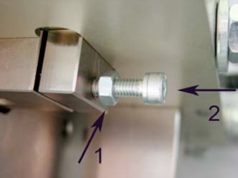
Tighten the counternut (1) again and then tip „tool in“ to check the position. 


The correct setting!


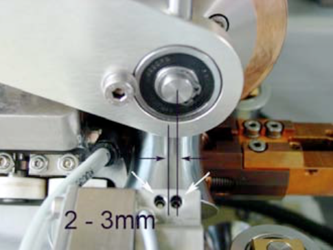
An alternative spot to measure the correct distance is below the tooling plate:

X = 82 – 83 mm.

All Can Man content is now also available on the Soudronic Group website.
Where do you want to continue your journey?
All Can Man content is now also available on the Soudronic Group website.
Where do you want to continue your journey?