Problem:
The push fingers to feed the stripes into the 2. operation do not work or do not always work properly and no error message appears.
Possible Causes & Resolutions:
Possible solutions:
The motherboard battery is a CR2032 lithium-metal cell. It is used to supply power to the clock integrated on the motherboard. If the battery is depleted or missing, the date and time are displayed incorrectly. Recommendation for replacement interval is 5 years.
For instructions on how to replace the battery use the download link below. You will also find the correct battery type there.
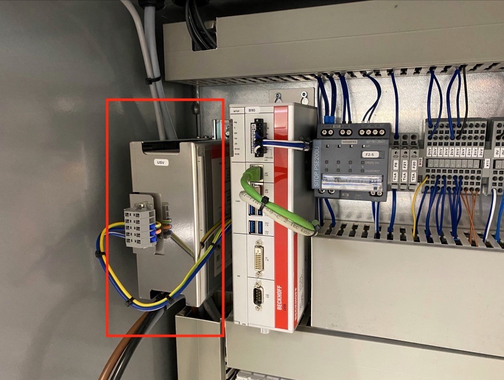
All Beckhoff control units are equipped with a UPS to ensure the proper shutdown of the control IPC. However, this only works if the battery is in perfect condition to prevent data loss and ensure the flawless operation of the control system. The battery module for the UPS must be replaced every 5 years.
To order a new battery please contact spares.canman@soudronic.com.
For instructions on how to replace the battery use the download link below. You will also find the correct order number there.
Problem:
The sheet is lifted by the front sucker bar but then dropped instead of being pushed into table 1. After 3 times slitter stop and error message “SEPARATION: Double sheet counter limit” appears.
Possible Causes & Resolutions:
Problem:
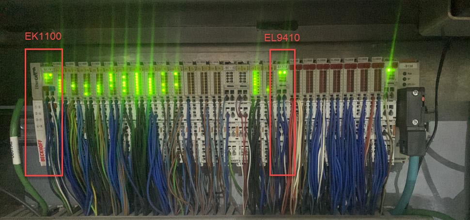
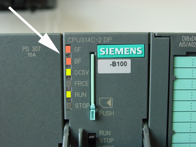
Some Beckhoff i/o terminals are not active and status LEDs are off, control does not respond to commands.
Possible Causes & Resolutions:
Problem:
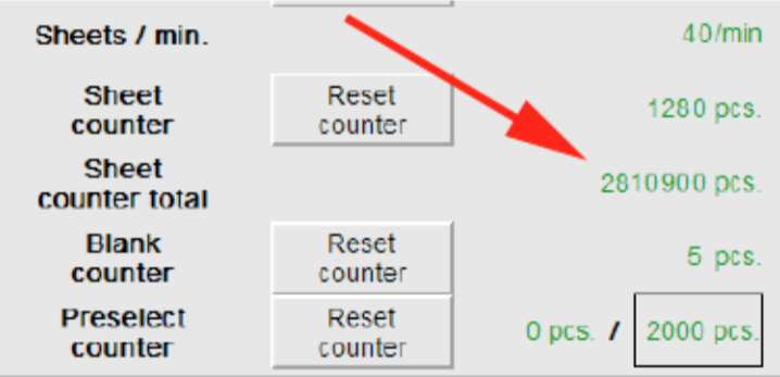
After main switch off and on again, HMI piece counter values and settings are lost or old recipes are loaded.
Possible Causes & Resolutions:
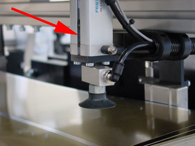
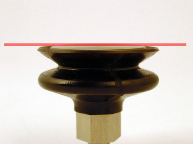
Problem:
Suction cup malfunction.
Vacuum not working, constantly on or constantly blowing air instead of (sucking and then blowing) once only.
Possible Causes & Resolutions:
Components:
KA1.2-1.7 Relays
Y108 Vacuum blank feeder back
Y109 Vacuum blank feeder front
Y110 Vacuum 1.Table
Y111 Blow off blank feeder back
Y112 Blow off blank feeder front
Y113 Blow off 1.Table
Spare Part:
003246 Relay / terminal 1 two – way contact
https://www.canman.ch/shop/shop-search/query/003246/?q=003246&search=Search
010482 Vacuum suction injector (Y109/Y112)
010486 Vacuum suction injector (Y108/Y111, Y110/Y113)
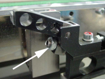
Problem:
Drives start but the slitter does not start cutting in automatic mode. Pockets on sheet collector are full but stacks are not pushed out automatically and the button on the panel for pushing out manually does not work either.
Possible Causes & Resolutions:
![]()
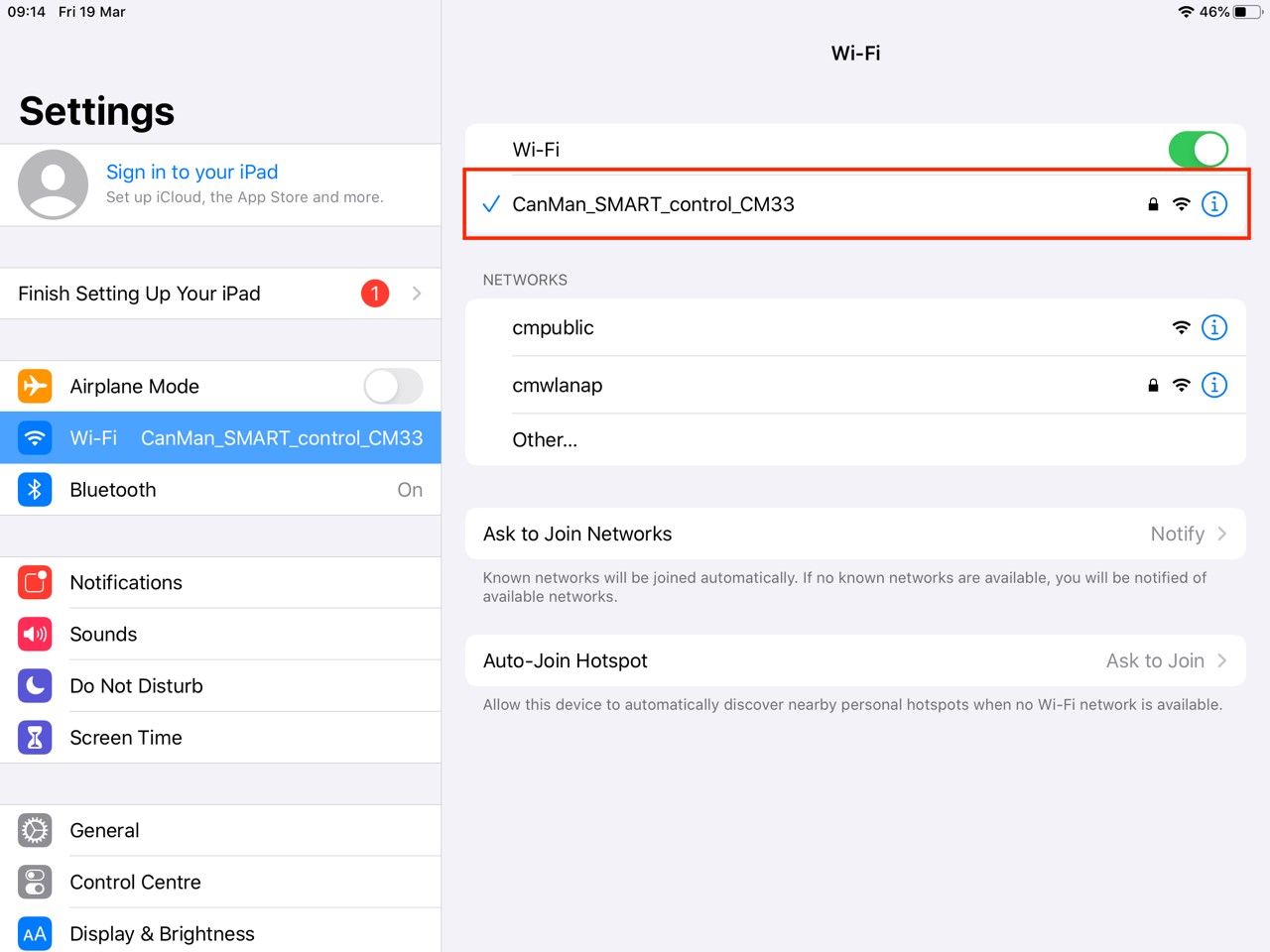
Problem:
The HMI cannot be started and the browser shows „NOT FOUND, The requested URL /en/default.htm was not found on this server“.
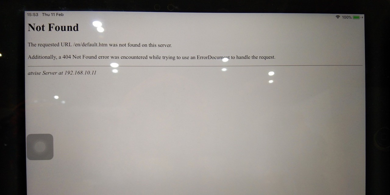
Possible Causes & Resolutions:
Not connected to Canman Wifi (only for wireless connected iPad’s): Check the wifi settings. Choose Canman wifi and try again.
IPC has not shut down correctly: In this case probably the HMI software can’t start up automatically by restarting the machine.
Check the IPC after you switched off the main switch: Normally it will continue to run for at least 30 seconds to shut down correctly. If LED’s of IPC goes off within a few second, the battery of the UPS – unit is dead and needs to be replaced. Contact Canman for online support to restart HMI.
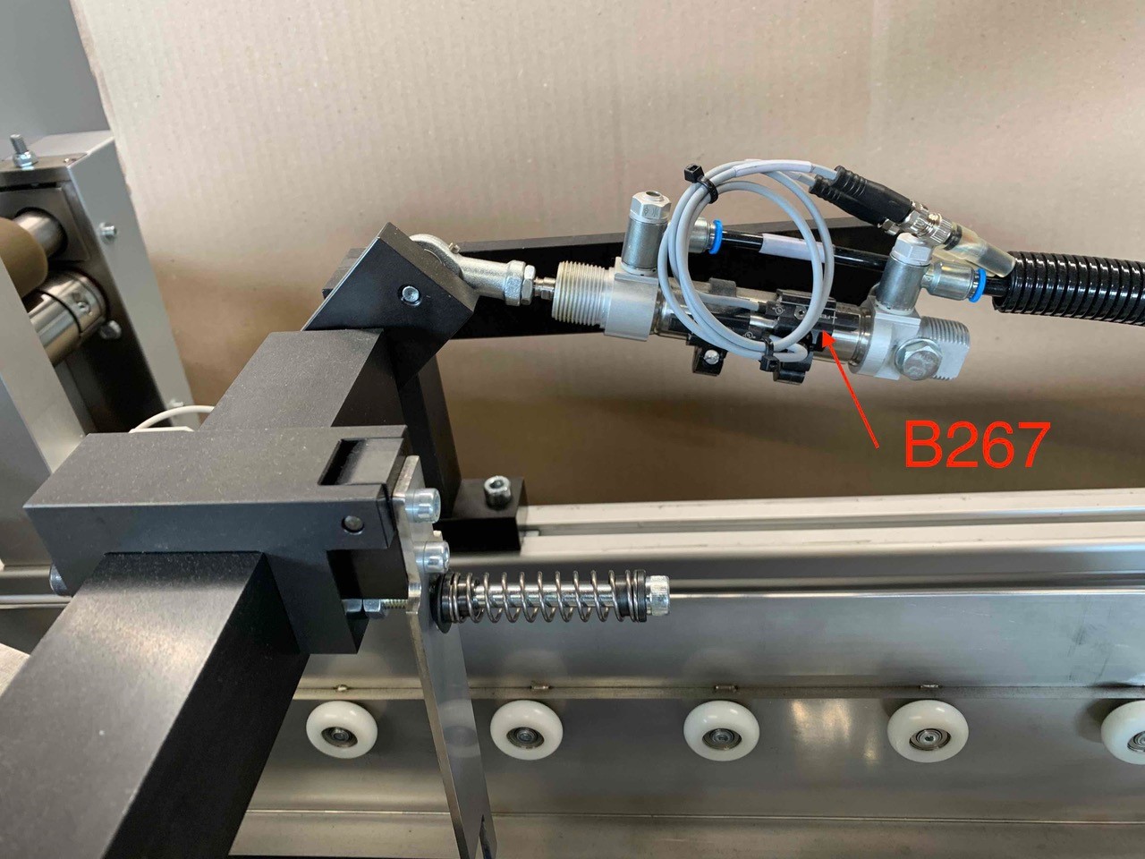
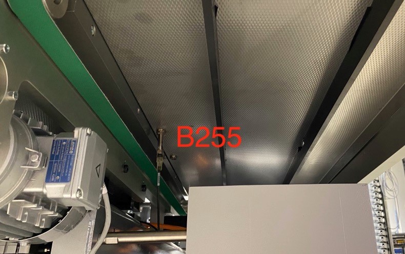
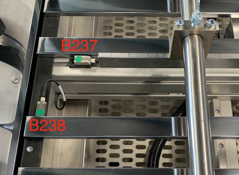
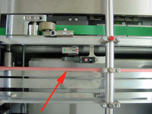
Problem:
First operation feeds the stripes too early into the upper magnetic belt of 2. table. Therefore the stripes do not stop on the upper magnetic belt and will be ejected through the slot in the frame of the 2. table.
Possible Causes & Resolutions:
Sensor B255: This sensor sends a signal to the control that the upper magnetic belt is ready for new stripes. The sensor might be defect or wrong adjusted.
Sensors B237 and B238: Sensor B237 does slow down the sheets and B238 stops the sheets for the centering. If the sheets do not stop, they may run through the first operation without being centered and with incorrect timing. The sensors might be defect or wrong adjusted.
Problem:
Everything looks fine but the drives do not start if the green button “Production On” is pressed.
Possible Causes & Resolutions:
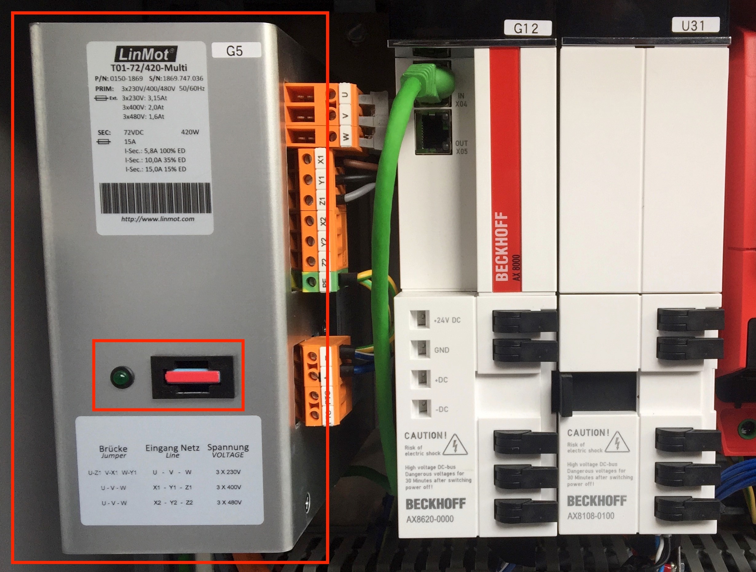
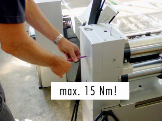
The main power supply 72 VDC of the Linmot controller is missing:
Check the power supply G5 inside the control panel on the second table (see attached picture). Most probably the 15 Amp. fuse is melted. Replace the broken fuse with a new one.
Problem:
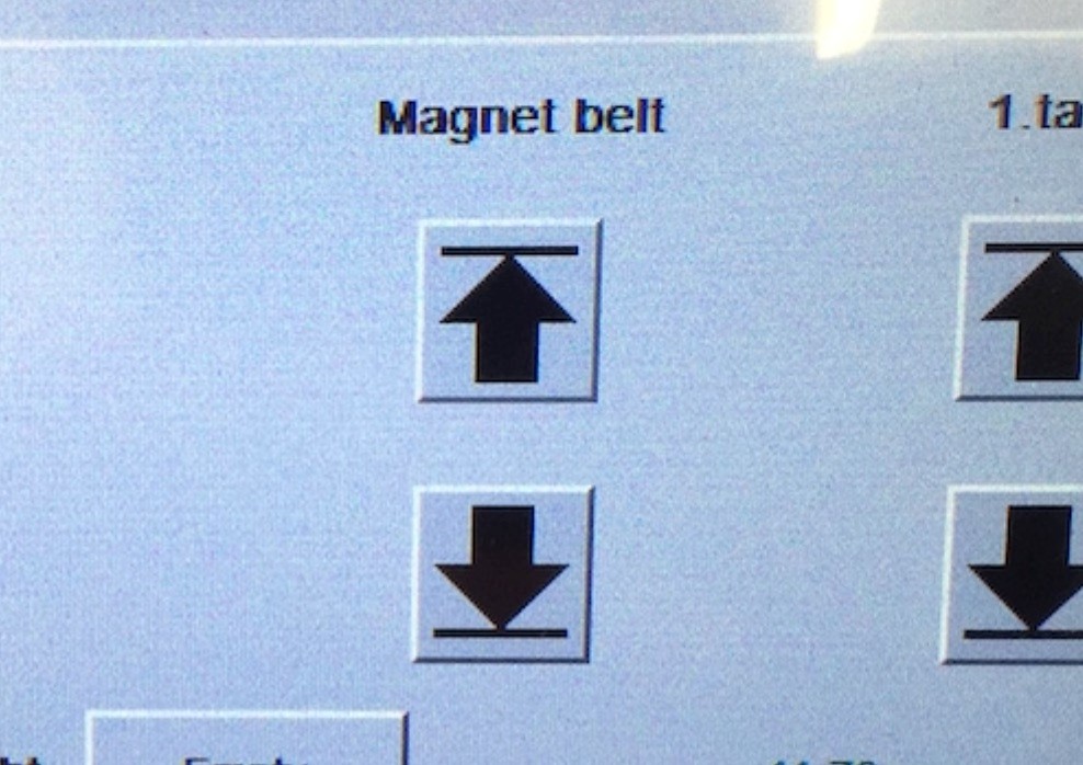
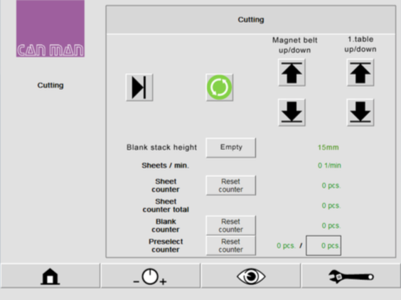
Error message „Magnet belt not down” displayed on HMI (magnet belt does only exist on the 2. table on a duplex slitter), and arrow buttons „Up” and „Down” for magnet belt are not visible anymore.
Possible Causes & Resolutions:
Arrow buttons magnet belt up may be visible for a short time and pushed during start up of panel.
Delete of error message:
Problem:
Possible causes & resolutions:
Note: If you use a new iPad the icons for the machine type can be produced, when you tap on “Add to home screen“ button.

Problem:
Display shows „Could not activate iPad“
Possible causes & resolutions:
For connecting an alternative display / PC, please have a look at the separate FAQ.
Problem:
iPad does not connect to the machine. Screen remains gray and shows no values.
Possible Causes & Resolutions:
Battery of IPC is empty when:
To Do:
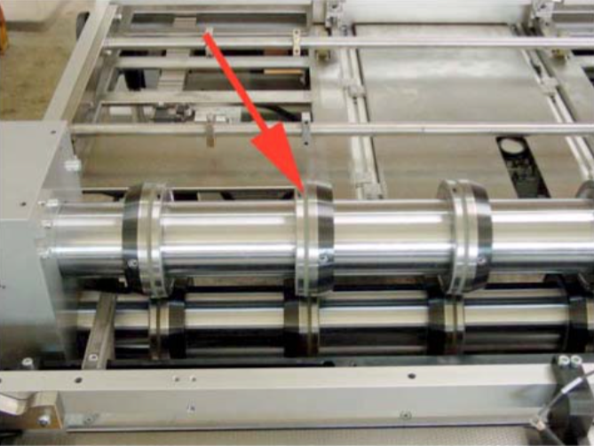
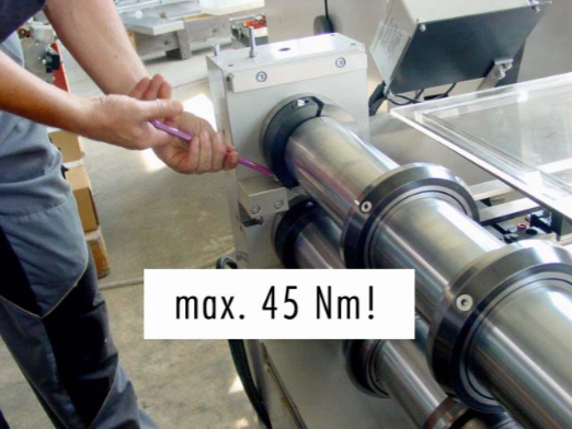
Note the adjustment of the clearance of the roller after the BIG8 monobloc cutting heads is ELEMENTARY to prevent bow cuts!
Check if the roller is not “tilted” (and thus one-sided “in the air”), refer also to manual of your slitter how to adjust the roller.
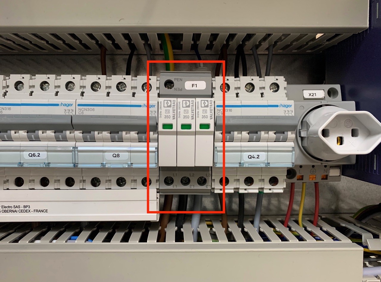
An overvoltage suppressor (or surge suppressor) is an appliance designed to protect electrical devices from voltage spikes. A surge suppressor attempts to regulate the voltage supplied to an electric device by either blocking or by shorting to ground voltages above a safe threshold.
These surge suppressors are built in to the latest Pacemaker models and machine controls (from 2009).
Check, if one or more modules of the surge suppressors are red/defect. Replace the red modules.
Attention!!!
Do not bridge the signalling contacts and run the machine with defective red modules because they no longer protect the system from voltage peaks!!!
If the modules are defective, check the main supply. Measure and check all voltages between the phases and all phases to earth before exchange the modules and restart the machine.
Possible causes:
Preparing of LAN or WLAN access:
How to start panel/HMI software:
Note: Panel Software is starting in Demo mode and does work for 60min only. After that it has to be restarted. To run the HMI without time limit you need a new license or if the original panel is not in use anymore the license can be transferred with the designated form:
Setting up of a new device in case of an unserviceable device:
! Attention ! The recipe from the unserviceable device is lost.
NOTE:
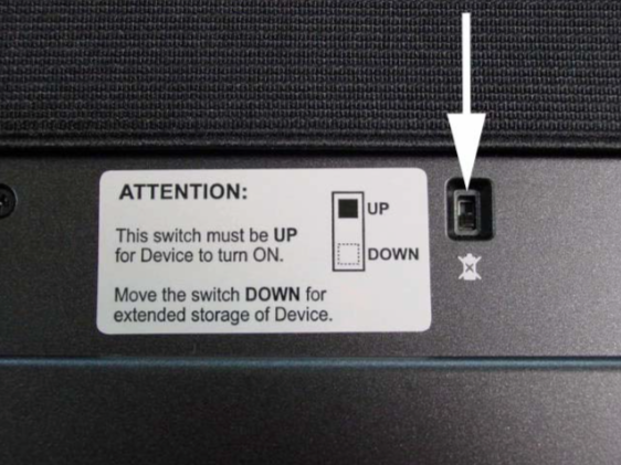
If you do not use the panel for a longer period (several weeks), the device should be turned off on the backside. Otherwise the internal battery will discharge and will get damaged!
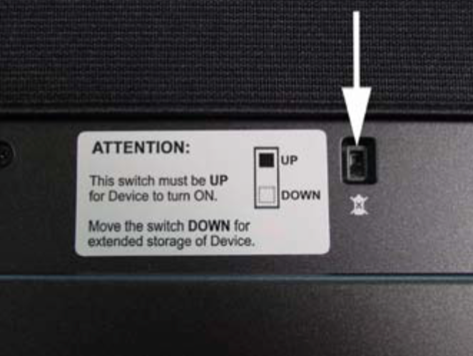
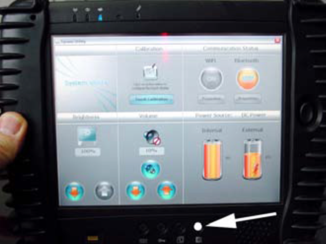
If you push the button on the right side, you are able to see the status of the integrated battery and optional available second battery.
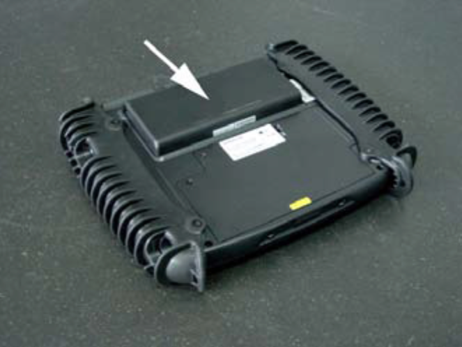
The optional second battery is located at the back of the device.
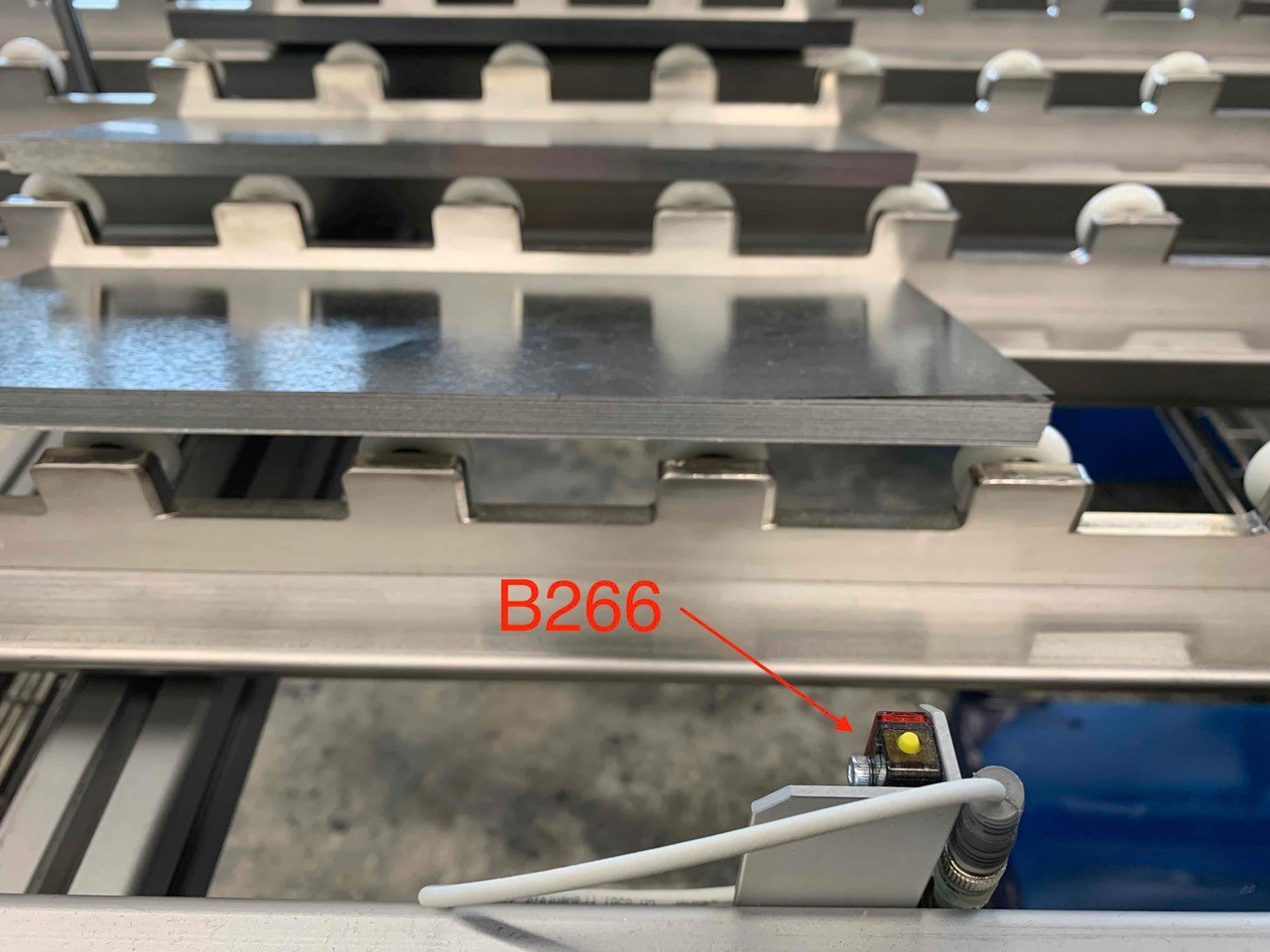
Possible causes:
Check function of the reed sensors B256, B257, B258 and B259.
You can find them on the cylinders of the magnetic conveyor (Y125) and transport roll (Y124). Manually activate the two cylinders on the valve block and adjust the reed sensors if necessary.
Refer also to the pneumatic diagram here.
Possible causes:
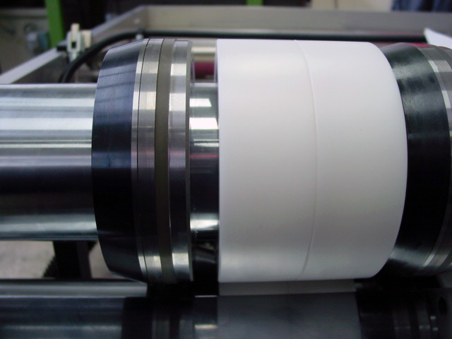
Check the transport rings on the knives: If the rubber is too small (due to heavy wear) conical or much bigger (if no original spares are in use) cutting tolerances can be negatively affected!
Make sure that enough support rings are mounted between the knives. They keep the sheet leveled. The thinner the sheets, the more important it is to keep them flat.
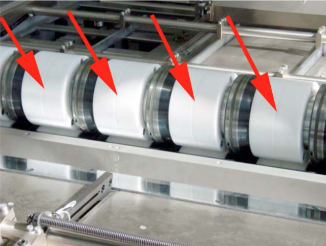
Make sure that all knives are well grinded.
NOTE:
You should regrind your cutters after approx. 3 mio. sheets.
Please check also Cutting results out of tolerance (standard knifes and BIG 8)
Possible causes:
1. Clearance between the upper and lower cutter is too small – min. 1/100 mm.
2. The bearings of the roller cutter have play => they need to be free of play!
3. The roller cutter shaft is heating up differently!
a) Something touches the roller cutter => slowly turn the roller cutter by hand
b) the bearing is heating up too much => bearing defect!
c) If you have an exchange roller cutter => the roller cutter shaft might not be fixed properly to the side.
=> or the roller cutter shaft is too tensely assembled!
Switch the battery “ON” on the backside of the touch-panel.
Start the touch-panel.
Click on this symbol. ![]()
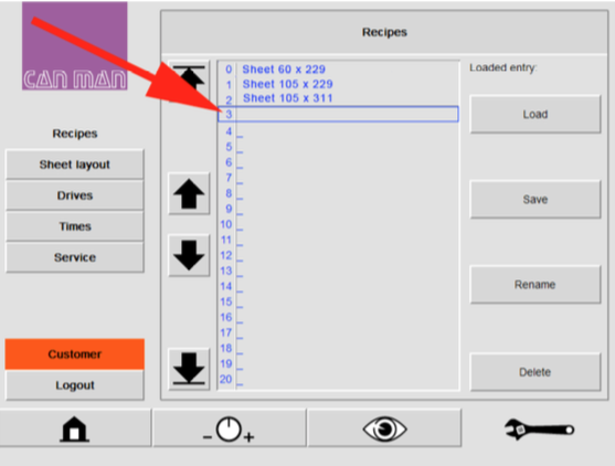
Click on the “CUSTOMER” key.
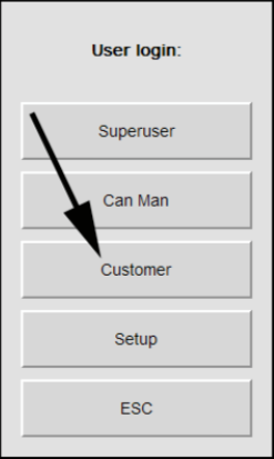
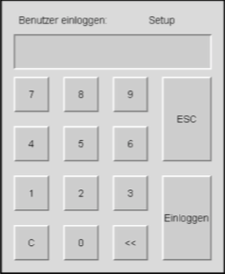
Login with your password.
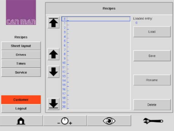
After you push the tool button once more, you can see the recipe window. ![]()
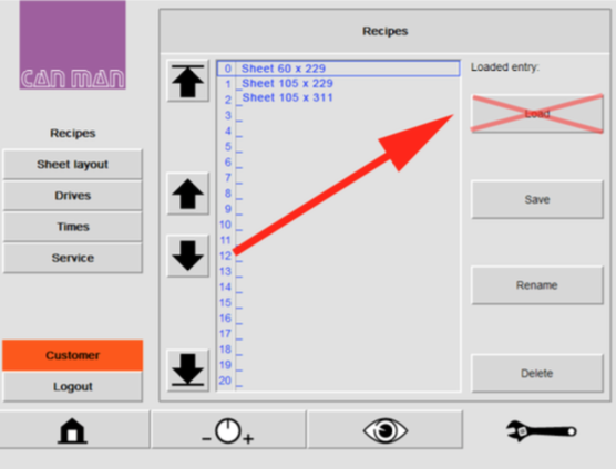
WARNING:
Do not push the load button. In this case you load an empty recipe and all parameters are set to 0 and you are not able to set back!
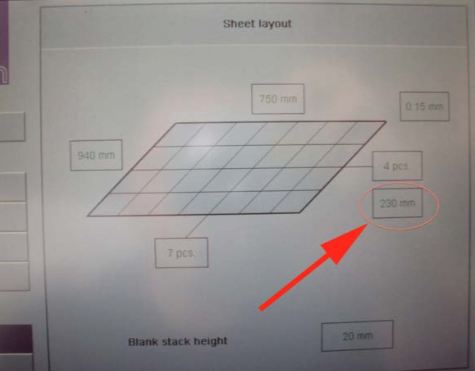
Choose a free memory space.
In this example 3 (blue coloured frame)
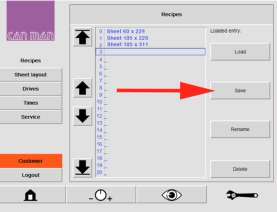
Push the „SAVE” button and a keyboard field will appear.
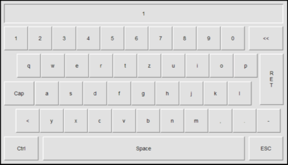
Enter a name for your program, e.g. „TEST“ and press the return key.
Confirm the entry with “Yes” or “No”.
NOTE:
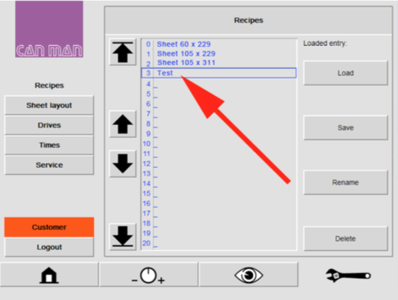
Now you can see the saved recipe on the list. You have saved the actual sheet parameter incl. the basic parameters of the PowerCUT.
Possible cause:
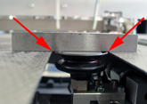
Possible causes:
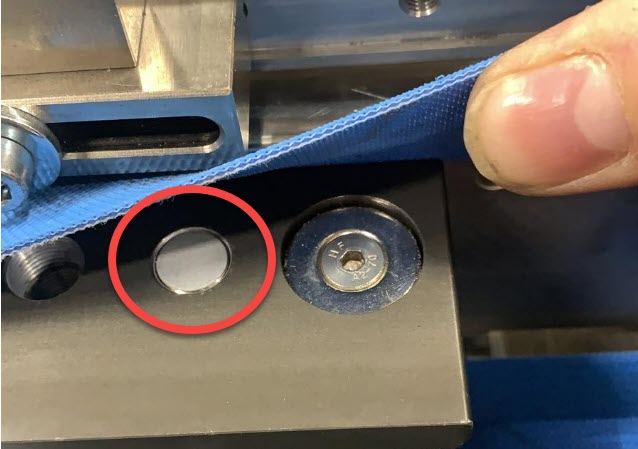
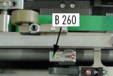
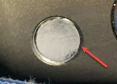
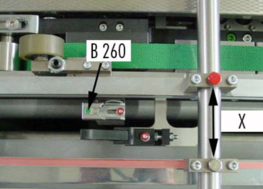
Make sure that the lateral, adjustable top guides (picture) are set correctly in lateral position as well as in height. They shall guide and hold the stripes as flat as possible over both sensors B260 and B261. Both sensors need to be reached at same time, otherwise the error will occur.
If the lateral guide is too far away from the sensor, the sheet might bulge. Therefore move the lateral guide closer to the sensor.
NOTE:
Do not loosen the screw marked red. The standard setting for top guide should be approx. X = 72 mm.
– Make sure that pressing rolls are adjusted correctly (picture).
– Check the movements of the sheet, they might get stuck somewhere.

Possible cause:
NOTE:
If you have too few magnets, it might cause angularity problems!

Damages at the front edge:
NOTE:
Do not loosen the red marked screw. The standard setting for top guide should be approx. X = 72 mm.

Possible causes:
Find a complete error list together with the interpretation of the error codes
Download PDF here
Possible causes:
Possible causes:
NOTE: The SQM measuring device can only detect “angular” cutting errors!
Possible cause:
Possible cause:
– bus connector limit switch not set correctly – address and dip switches not set according
to the electrical scheme (bus subscriber) – wire defect
– bus connector defect
– bus modul or subscriber defect.
To narrow the error you have to check the status with all the subscribers.
To test, switch the limit switch into the bus connector => the bus runs now to the corresponding subscriber, e.g. “Lenze inverter” which the LED flashes yellow.
If you are able to narrow in the error, exchange the corresponding components.

NOTE:
Do not forget to set the parameter and the dip switches accordingly. The parameters are mentioned in the electrical scheme!
BF LED (red) not active
Lenze inverter:
LED upper-left must light up (green)
LED upper-right must be flashing (yellow)
LinMot:
Error LED not active or no error code profibus

Beckhoff Control:
For the Beckhoff Control, please refer to this PDF for instructions.
Please refer to “User Manual Motion Control Software” for the error codes of the MC Software. The PROFIBUS Interface has the following additional error codes:
Error code hexadecimal: Error description: C1h Fatal error: Drive not supported
C2h Config error: Invalid MACID
C3h DP Err: Connection lost

Setting gauge for blank magazine
The setting gauge allows faster adjustment of the blank magazine. This file can be used as a template for individual manufacturing according to specific formats.
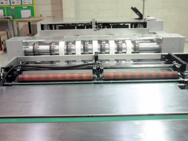
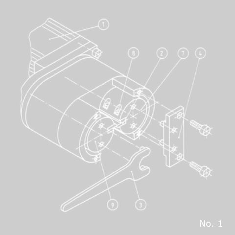
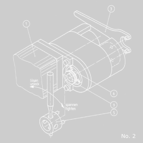
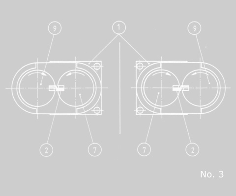
To remove the used cutting blades, two spherical clamp screws M6 (8) have to be loosened. The steps for the fitting of the fixing plate (4), which is part of the standard tools delivered with every slitter, are:
Important
During the assembly of the new cutter blades (2) check that the ahead running blade is on the motor driven cutter shaft (7). See picture no. 3
Nobody should start the unit during the set up. The emergency button should be pressed down, the key-operated switch taken away from the slitter.
Non-compliance of this instruction will cause cutter blade damage or blocking of shafts.
Possible causes:
